I have not seen this posted.
Navigation
Install the app
How to install the app on iOS
Follow along with the video below to see how to install our site as a web app on your home screen.
Note: This feature may not be available in some browsers.
More options
Style variation
-
Congratulations TugboatEng on being selected by the Eng-Tips community for having the most helpful posts in the forums last week. Way to Go!
You are using an out of date browser. It may not display this or other websites correctly.
You should upgrade or use an alternative browser.
You should upgrade or use an alternative browser.
Norway bridge collapse 17
- Thread starter dylansdad
- Start date
- Status
- Not open for further replies.
-
1
- #81
Don't do much glulam, but here is links to free design manuals used for glulam in Norway (probably based on EC5).
Could contain some justifications for using small dowels.
- design manual, connections start on page 243
- calculated examples
Could contain some justifications for using small dowels.
- design manual, connections start on page 243
- calculated examples
-
1
- #83
Another animation to clarify the issue with node 13 (though using a photo of node 31). While the upper structure is firmly held by the support, the lower chord is not. What starts as a flexing about the node will deteriorate into wholesale movement as the pin connections round out. This places additional burden on node 14. How far the deterioration at 13 progresses before node 14 fails is unclear however I believe the progression to failure is not.
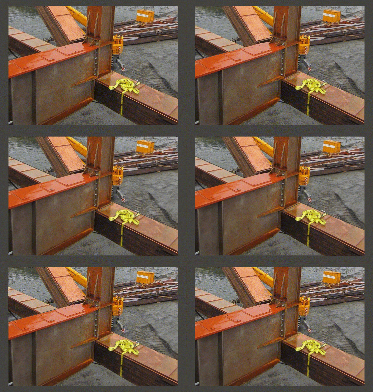

From Facebook, a photo revealing node 13 pin connection - There are only ten pins
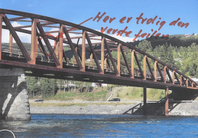
Råg Stevra (This appears to be a copy of another photo posted by Moelven Limtre AS in 2016)
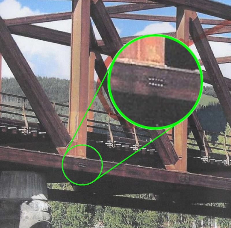

Råg Stevra (This appears to be a copy of another photo posted by Moelven Limtre AS in 2016)

The lower chord didn't even have to rip out of the connection, it might just split along the centerline/delaminate and loose its ability to carry a compressive load.
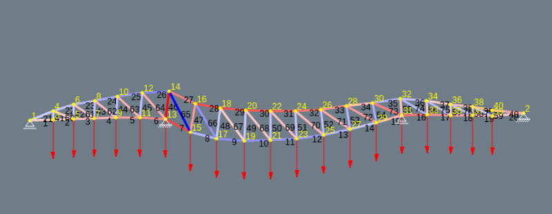
A visible stub of the lower chord appears to have lost about thirty percent of its depth.
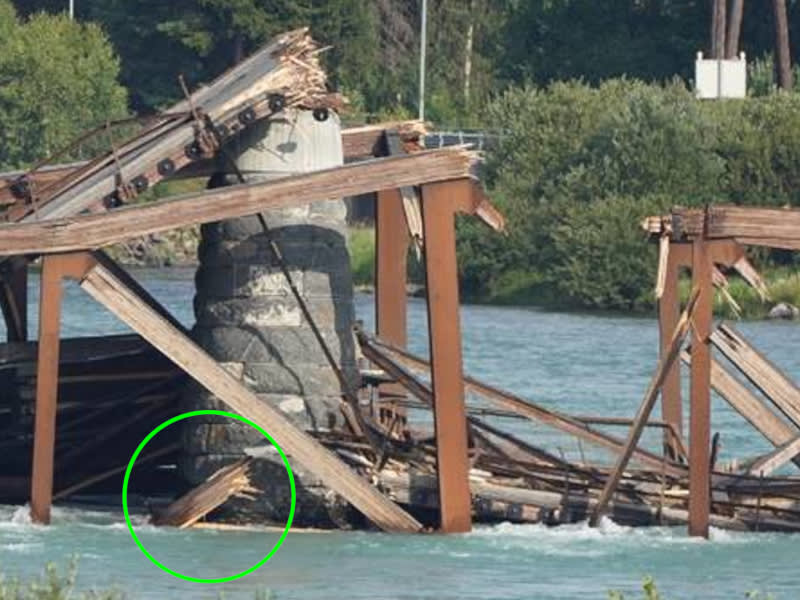
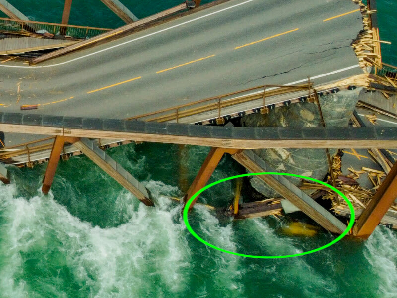
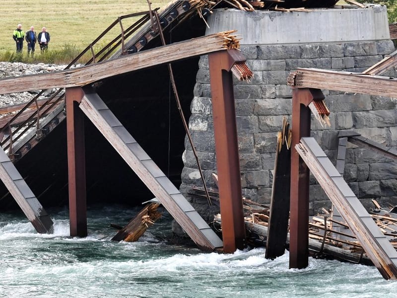
The delaminated timber leaning on the left side of the 15/16 vertical may be from the lower chord as well. That could be determined if the width could be reliably compared with another known item.

A visible stub of the lower chord appears to have lost about thirty percent of its depth.


The delaminated timber leaning on the left side of the 15/16 vertical may be from the lower chord as well. That could be determined if the width could be reliably compared with another known item.
-
1
- #87
That has to be close to the conclusion. A design flaw at the west support resulted in crippling damage to the lower chord which allowed the center span to drop, snapping the upper chord and pulling out the diagonal at node 14 while the short western span collapsed and pushed the support frame east off the pier. The collapsing center span caused massive damage at the eastern support.
I saw your little animation of that joint, but a truss doesn't work like that. The horizontal component of the web member must be resisted by the chord, thus must be connected to the chord. Any actual details of that joint, or a photo from the outside?
... a truss doesn't work like that.
I should take that as a compliment since that's the whole purpose of this exercise.
Perhaps the road deck provided the horizontal stability for the supported frame while the chord connection deteriorated. I can't say I have all the answers but I find it curious that the wreckage seems to support the notion that the lower chord connection or the lower chord failed.
I'm posting as many relevant images as I dare without further overloading the space. Precollapse photos of the connection will be more difficult to find. The 2016 images look rather pristine.
I find it odd that there is no trace of the north/south diagonal members or the top chord sections left in the wreckage. If the leaning piece I mentioned earlier is part of the bottom chord, that too would be odd (as is any piece leaning up like that) since the diagonal would have to get out of the way first before anything else could occupy that space.
I believe the weight of the truck initiated the collapse. It would be quite the coincidence for the bridge to start its failure just when this heavy load was on it. Put another way: what percentage of time was that bridge supporting a load like that?
If the bridge failed near the masonry pier, the truck that caused that action was already gone. I ballpark the time at 7 seconds (20 MPH).
So it would have taken several seconds between initiation and total failure.
Or.
The bridge failed under the truck almost immediately.
spsalso
If the bridge failed near the masonry pier, the truck that caused that action was already gone. I ballpark the time at 7 seconds (20 MPH).
So it would have taken several seconds between initiation and total failure.
Or.
The bridge failed under the truck almost immediately.
spsalso
This looks like a truss, but the upper and lower cords are continuous and all of the vertical and diagonal connections will carry some moment (until the pins split the cords).said:... a truss doesn't work like that.
I suspect the actual behavior is between that of a truss and a continuous beam with 4 supports. This may be important as the bending moment for a continuous beam with 4 supports will be significantly less than a simple beam supported on it's ends.
Actual load transfer at the supports depends on position and spring rate of the components, and significantly impacts the member loading.
The behavior at the initial failure (early reported movement), was followed some time later by the collapse, which may hide the initial failure to some extent.
-
1
- #94
I often design trusses with continuous top and bottom chords... with web members pinned... It could very well have been designed in that fashion.
![[pipe] [pipe] [pipe]](/data/assets/smilies/pipe.gif)
So strange to see the singularity approaching while the entire planet is rapidly turning into a hellscape. -John Coates
-Dik
If this failure was caused by a single truck that suggests a significant design error. Bridges are designed for accidental loads, lane loads, specific vehicles and many other load cases. The truck pictured in the collapse does not seem to be oversized truck nor overloaded. Like the other failures discussed in the thread, I believe it will boil down to a node error.
This obsession to use the minimum size and number of bolts is perplexing. What cost would the bolts be in a bridge like this? If they did use a 1/2" bolt that just seems nuts.
This obsession to use the minimum size and number of bolts is perplexing. What cost would the bolts be in a bridge like this? If they did use a 1/2" bolt that just seems nuts.
Those pinned spline joints have no constraint in the axes perpendicular to the member.
For example, if the pins WERE bolts, the bolts could be tightened up so as to provide friction between the wood and steel plates, and also lessen any gap between the wood and steel. That gap will lessen the effectiveness of the shear connection transferring force between wood and steel through the pin.
The joint is also not constrained in the direction 90 degrees to the pins and to the member. Thus if there is moment in that joint, the wood is allowed to expand from the forces delivered, and will be more likely to crack along the row(s) of pins.
spsalso
- Status
- Not open for further replies.
Similar threads
- Replies
- 13
- Views
- 13K
- Replies
- 17
- Views
- 11K
- Replies
- 33
- Views
- 3K
- Replies
- 1
- Views
- 858
- Locked
- Question
- Replies
- 1
- Views
- 2K

![[ponder] [ponder] [ponder]](/data/assets/smilies/ponder.gif)