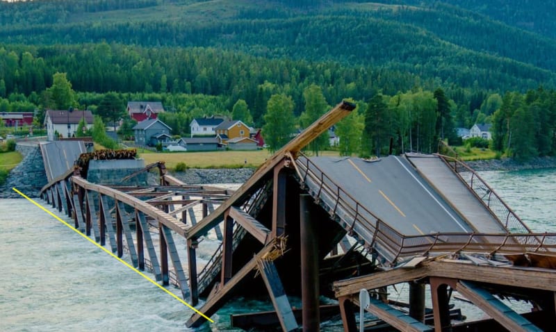
I have not seen this posted.
Navigation
Install the app
How to install the app on iOS
Follow along with the video below to see how to install our site as a web app on your home screen.
Note: This feature may not be available in some browsers.
More options
Style variation
-
Congratulations TugboatEng on being selected by the Eng-Tips community for having the most helpful posts in the forums last week. Way to Go!
You are using an out of date browser. It may not display this or other websites correctly.
You should upgrade or use an alternative browser.
You should upgrade or use an alternative browser.
Norway bridge collapse 17
- Thread starter dylansdad
- Start date
- Status
- Not open for further replies.
LittleInch
Petroleum
Always difficult in these to know what is potential cause and what is effect.
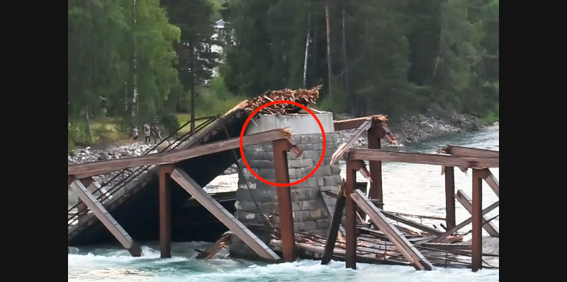
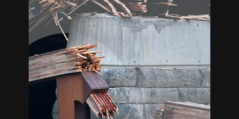
That picture is very interesting in terms of what happened to the end of the cross beam that sits on those new piles.
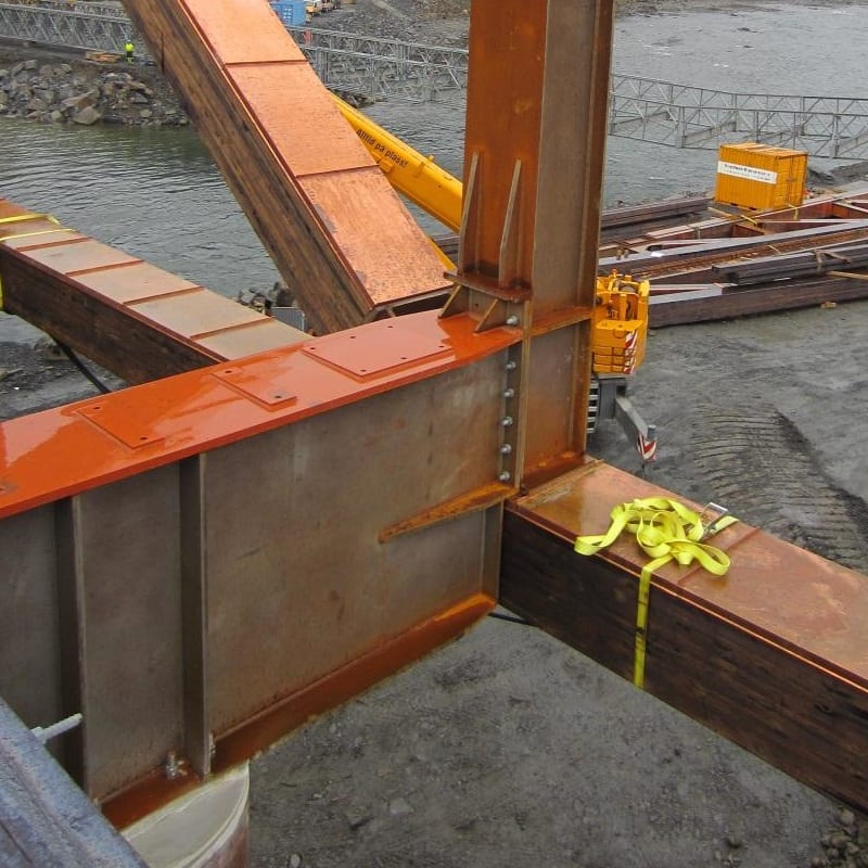
The original construction (see photo several posts ago from me) appears to show only 12 rather weedy looking bolts and some small webs transmitting the force from the truss structure to the piles.
The current picture shows the end just sheared off.
But maybe that nearer pile has simply been beaten into the ground more than its partner due to it being the one taking more of the load than the other?
So when trucks went across the truss flexed down to hit the top of the pile?
Plenty for the investigators to consider, but we're really missing a collapse video.....
Remember - More details = better answers
Also: If you get a response it's polite to respond to it.
I now see the damage you are referring to. It is very interesting and there are plenty of images. I'll work on it later.
That is a lot of trouble (the joint looks as though it fell apart), but I struggle to see how that happened, prior to collapse or otherwise. A model with the support missing might be more helpful than a model of a functional structure.
The reports of bridge movement prior to collapse are more ominous and speak to the unresponsiveness of a monitoring system that "just did inspections this year". Maybe when something changes, there needs to be another inspection.
That is a lot of trouble (the joint looks as though it fell apart), but I struggle to see how that happened, prior to collapse or otherwise. A model with the support missing might be more helpful than a model of a functional structure.

The reports of bridge movement prior to collapse are more ominous and speak to the unresponsiveness of a monitoring system that "just did inspections this year". Maybe when something changes, there needs to be another inspection.
Node 14
Google Maps
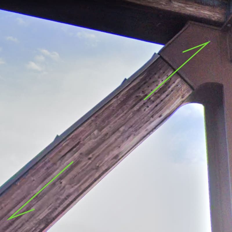
My question is, how well can this connection be relied upon to hang a truck, or a truck and a bridge?
That is not to say that a failure at node 15 wouldn't cause this damage, it would.


Google Maps
My question is, how well can this connection be relied upon to hang a truck, or a truck and a bridge?
That is not to say that a failure at node 15 wouldn't cause this damage, it would.
I went to research a bit about Perkolo bridge collapse. It was due to design error, where they misread joint design force. Basically they designed one part of a joint for half the force they should. Scary.
[link]https://www.slideshare.net/AdityaSanyal3/large-span-structuresnew]Starts at around slide 70[/url]
Look at slide 67. These dowel connections are really strong. Use multiple steel plates and you get more shear planes. Problem is if moisture stays trapped somewhere. That's my main fear with bridges.
Cool_Controls
Electrical
I'm guessing the flow of the river may have pushed it a bit south.
To summarize, the lower truss chord tore out of its connection at the "reused pillar" support resulting in complete structural failure . Possibly a design error.
I tuned up the model and also solved the mystery, I think!
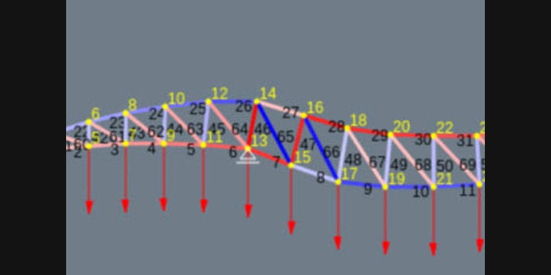
Again, I used some numbers from the pdf linked to earlier (and attached below) and scaled the slope and top chord from the drawings in same. Most of the nodes correlate to those in the drawing in the report, the exceptions being the endpoints 1 and 2.
The slope is approximately 2.24 meters down to the west (left). The modeling software is online here.
To control the display, I've started with the support at node 13 constrained in the x direction (I have yet to learn how to tame the exaggerated displacements). I believe the structure is anchored at node 2.
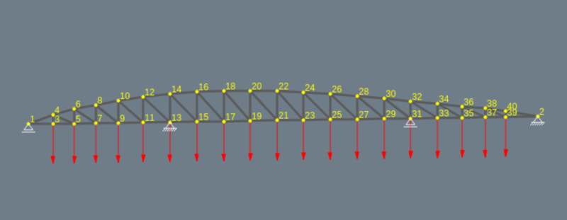
I applied a distributed load of 1 unit to represent the self weight of the structure. I then applied a series of loads of 10, 20 and 10 units at nodes 13, 15, and 17 to represent a loaded lorry and trailer. These loads coincidentally result in a convenient display. The results are displayed below. Although the support at 13 is constrained, suffice it to say that an unrestrained support would be displaced west (left).
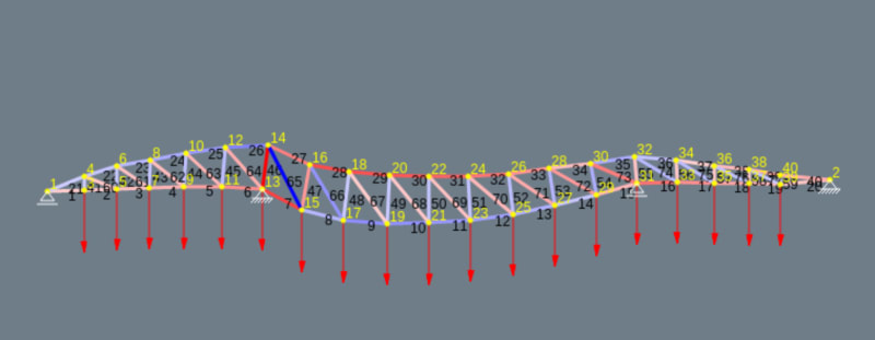
Next is the mystery solution.
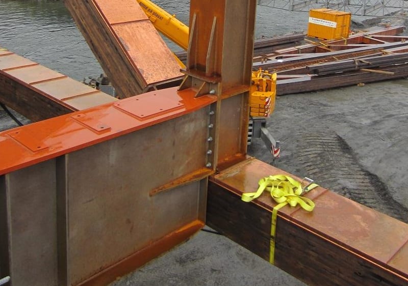
As can be seen in the image below, the lower chord connection at node 31 is for all intents and purposes hung off the bottom of the support. The same detail exists at node 13 ... and bad trouble ensues.
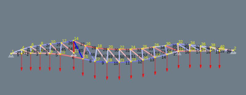
Since the structure is not pin connected and the top/bottom chords have significant stiffness, they cannot accommodate sharp turns, such as that anticipated across the support at 13 (see results above). The only recourse for the lower chord at that point is to tear free of the connection. The result is shown below. Again, the support at node 13 is fixed to aid the presentation.
This also explains the damage at node 14 where the top chord snaps across the vertical web member and the diagonal tears away from its connection.
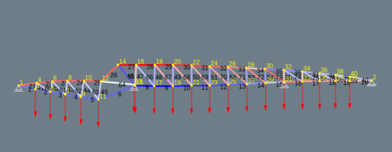
Also, when the support at node 13 is freed from its constraint, we see the node kicks significantly to the east, which is what happened in real life as the frame was significantly displaced off the pier.
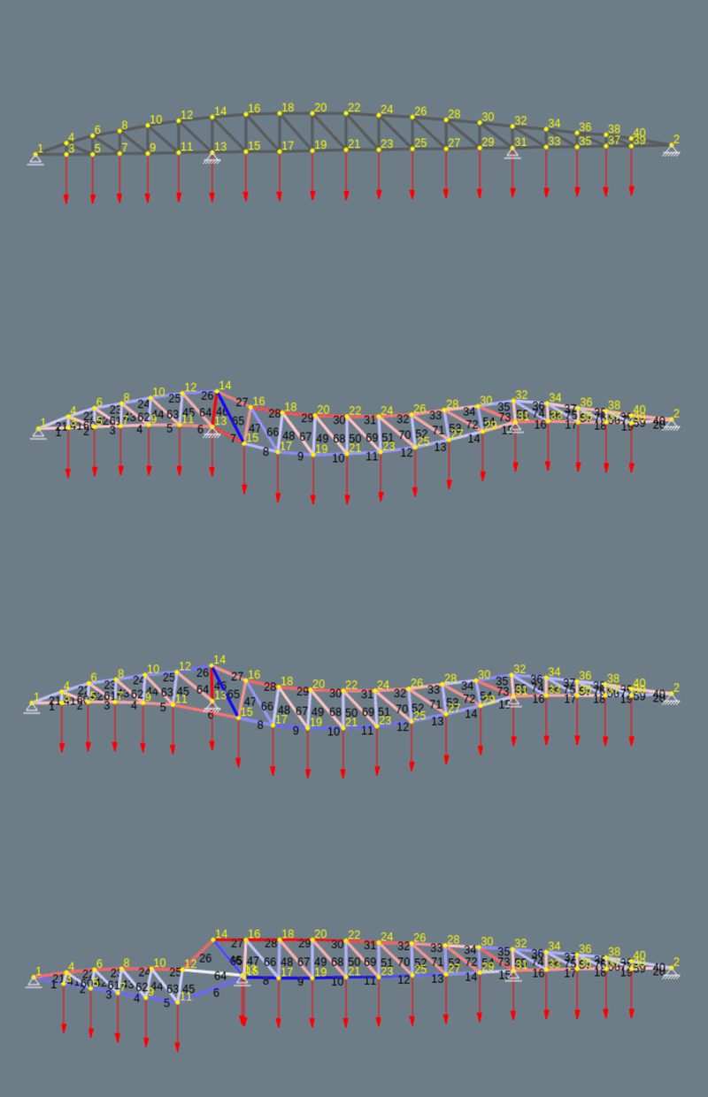
I don't believe a single trip, even by an overweight vehicle, is responsible for this collapse, rather, the issue developed over time and this one heavy vehicle was the unfortunate last straw.
To summarize, the lower truss chord tore out of its connection at the "reused pillar" support resulting in complete structural failure . Possibly a design error.
I tuned up the model and also solved the mystery, I think!
Again, I used some numbers from the pdf linked to earlier (and attached below) and scaled the slope and top chord from the drawings in same. Most of the nodes correlate to those in the drawing in the report, the exceptions being the endpoints 1 and 2.
The slope is approximately 2.24 meters down to the west (left). The modeling software is online here.
To control the display, I've started with the support at node 13 constrained in the x direction (I have yet to learn how to tame the exaggerated displacements). I believe the structure is anchored at node 2.

I applied a distributed load of 1 unit to represent the self weight of the structure. I then applied a series of loads of 10, 20 and 10 units at nodes 13, 15, and 17 to represent a loaded lorry and trailer. These loads coincidentally result in a convenient display. The results are displayed below. Although the support at 13 is constrained, suffice it to say that an unrestrained support would be displaced west (left).

Next is the mystery solution.
As can be seen in the image below, the lower chord connection at node 31 is for all intents and purposes hung off the bottom of the support. The same detail exists at node 13 ... and bad trouble ensues.

Since the structure is not pin connected and the top/bottom chords have significant stiffness, they cannot accommodate sharp turns, such as that anticipated across the support at 13 (see results above). The only recourse for the lower chord at that point is to tear free of the connection. The result is shown below. Again, the support at node 13 is fixed to aid the presentation.
This also explains the damage at node 14 where the top chord snaps across the vertical web member and the diagonal tears away from its connection.

Also, when the support at node 13 is freed from its constraint, we see the node kicks significantly to the east, which is what happened in real life as the frame was significantly displaced off the pier.


I don't believe a single trip, even by an overweight vehicle, is responsible for this collapse, rather, the issue developed over time and this one heavy vehicle was the unfortunate last straw.
To summarize, the lower truss chord tore out of its connection at the "reused pillar" support resulting in complete structural failure . Possibly a design error.
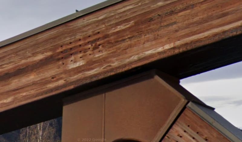
Have any details of the connections come to light? The picture which Little Inch posted showing 20 bolts each side of a splice doesn't look right from a timber detailing standpoint. The bolts seem too closely spaced in the lines parallel to the axial force. There is presumably something steel in the middle of that connection, but without shear plates or split rings, the capacity of bolts alone is not high.
As I posted earlier, six plates with thirty pins at node 14. Littleinch is showing a lighter assembly connection. In the report I recall an image with a truss section slung on a crane where the steel connection plates were visible.
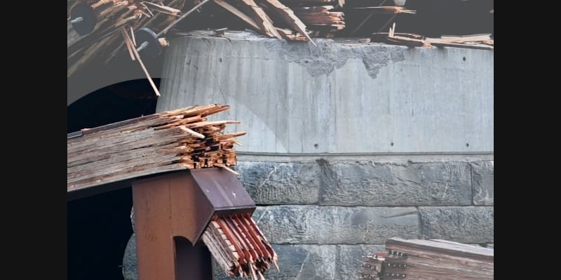
Edit: On page 25, buried behind another image, this:
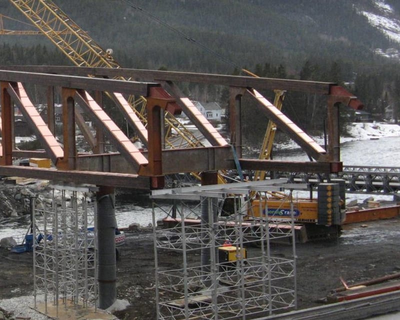
Edit: Another (and many more) on Google Maps here

Edit: On page 25, buried behind another image, this:

Edit: Another (and many more) on Google Maps here
In a connection like that, the capacity of the steel plates will be many times the capacity of the timber, especially with the bolts that close together and not staggered. Notice the discoloration along those bolt lines? That means something.
-
2
- #71
Bolts are close together to reduce splitting of timber. If bolts are spread out, steel plates hold bolts rigidly and when timber shrinks or swells it causes cracks. Also you reduce rotational stiffness with bolts together.
This makes me think.. with so much steel elements and rigid plates, is there a possibility the connections were too rigid and design didn't account for additional moments and shear? Also this structure is very sensitive to deformation of any kind.
This makes me think.. with so much steel elements and rigid plates, is there a possibility the connections were too rigid and design didn't account for additional moments and shear? Also this structure is very sensitive to deformation of any kind.
Retrograde
Structural
Sym P. le said:Since the structure is not pin connected and the top/bottom chords have significant stiffness, they cannot accommodate sharp turns, such as that anticipated across the support at 13
Have you modeled the chords as continuous? From your deflected shape it does not appear that you have. Therefore your results are somewhat meaningless.
That is a fair comment. If anyone can point me to (cough) free software that allows that, I'll redo the model.
Having said that, the model I used was not intended to be a replication to the finest detail but a tool to shed light on the tendancies of the structure. I may be overly bold in my statements but I hope others are open minded enough to recognize that, for example, the exaggerated displacements, aren't being suggested as an absolute fact.
Thanks for your response.
LittleInch
Petroleum
The fallen structure has definitely moved due to the water flow. you can see in the photo from Sym P Le the cross beam which was still sitting on the new piled support has now fallen into the river.
The joint connections don't look that good though - Black ends don't seem good to me.
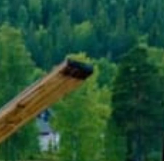
Remember - More details = better answers
Also: If you get a response it's polite to respond to it.
The joint connections don't look that good though - Black ends don't seem good to me.

Remember - More details = better answers
Also: If you get a response it's polite to respond to it.
Looking at that nice close-up of a connection posted above, I see only an array of small holes. Thus I don't imagine "bolts". More "pins". So then there would be no clamping pressure between the wood and the steel plates inserted inside--only shear.
I do hope that someone somewhere has duty cycled a sampling of this type of connection.
I also wonder how the joint was fabricated. I assume the through-holes were drilled after the pieces were assembled, so as to guarantee alignment for the pins. I count 6 steel plates inserted into one joint, so if you pre-drilled, you'd have LOTS of opportunity for misalignment.
spsalso
Four Norwegian reports from
Translation - note: "tretten" translates to thirteen so sometimes news reports indicate thirteen bridges were inspected when in reality the Tretten Bridge was inspected. On the other hand, references to twelve bridges being inspected are true.![[lookaround] [lookaround] [lookaround]](/data/assets/smilies/lookaround.gif)
Tretten bridge had an individual inspection on 3 June 2022, and a main inspection in 2021. The inspection was carried out by the county council, but the reports are entered into the Norwegian Road Administration's bridge management system Brutus.
Attached is an overview drawing of the Tretten bridge.
The report on the inspection of wooden truss bridges from 2016 may be of general interest. This is a review of all wooden truss bridges. The background for this was the collapse of the Perkolo bridge.
Also attached is the report prepared by the Directorate of Roads on the incident at Perkolo.
Inspeksjonsrapport Tretten bru.pdf - Inspection report Tretten Bridge
Oversiktstegning Tretten bru.pdf - Overview drawing Tretten Bridge
Kontroll av fagverksbruer i tre.pdf - Inspection of wooden truss bridges Discussions, findings and recommendations from the work
Perkolo bru sluttrapport.pdf - The collapse of the Perkolo bridge - what went wrong?
Translation - note: "tretten" translates to thirteen so sometimes news reports indicate thirteen bridges were inspected when in reality the Tretten Bridge was inspected. On the other hand, references to twelve bridges being inspected are true.
![[lookaround] [lookaround] [lookaround]](/data/assets/smilies/lookaround.gif)
Tretten bridge had an individual inspection on 3 June 2022, and a main inspection in 2021. The inspection was carried out by the county council, but the reports are entered into the Norwegian Road Administration's bridge management system Brutus.
Attached is an overview drawing of the Tretten bridge.
The report on the inspection of wooden truss bridges from 2016 may be of general interest. This is a review of all wooden truss bridges. The background for this was the collapse of the Perkolo bridge.
Also attached is the report prepared by the Directorate of Roads on the incident at Perkolo.
Inspeksjonsrapport Tretten bru.pdf - Inspection report Tretten Bridge
Oversiktstegning Tretten bru.pdf - Overview drawing Tretten Bridge
Kontroll av fagverksbruer i tre.pdf - Inspection of wooden truss bridges Discussions, findings and recommendations from the work
Perkolo bru sluttrapport.pdf - The collapse of the Perkolo bridge - what went wrong?
- Status
- Not open for further replies.
Similar threads
- Replies
- 13
- Views
- 13K
- Replies
- 17
- Views
- 11K
- Replies
- 33
- Views
- 3K
- Replies
- 1
- Views
- 857
- Locked
- Question
- Replies
- 1
- Views
- 2K

