I have not seen this posted.
Navigation
Install the app
How to install the app on iOS
Follow along with the video below to see how to install our site as a web app on your home screen.
Note: This feature may not be available in some browsers.
More options
Style variation
-
Congratulations cowski on being selected by the Eng-Tips community for having the most helpful posts in the forums last week. Way to Go!
You are using an out of date browser. It may not display this or other websites correctly.
You should upgrade or use an alternative browser.
You should upgrade or use an alternative browser.
Norway bridge collapse 17
- Thread starter dylansdad
- Start date
- Status
- Not open for further replies.
LittleInch
Petroleum
With no video of the collapse and lots and lots of collateral damage, finding the cause would appear to be very difficult to me.
The way they destroyed the eastern end to get the truck out and clear the main road has probably eliminated much evidence and a fair bit has gone into the river.
There was no apparent sudden trauma or incident - but the bridge suddenly collapsed. Trying to work out cause from effect looks to be very complex. Lots of options available....
Remember - More details = better answers
Also: If you get a response it's polite to respond to it.
hokie66 (Structural) 22 Sep 22 11:20 said:No, the heads are still attached.
I should be more careful with sarcasm, even if it's obvious the heads are still attached. If the heads literally popped off, that would indicate a defective product. Instead, the bolts are likely performing exactly to spec and some metallurgist is pumped that a run of product, or in this case two products, all performed like the identical little clones they are. I think the bolts are a side show to the main event, but an interesting study in themselves.
I hadn't realized that two bolts were spec'd. I'm guessing the top bolt is the heavier 10.9 while the main lower array is the lesser 8.8. I'm curious how they arrived at the quantities and what damage occurred that isn't visible in the photos (to the bolt plates). The bolt pattern seems to vary depending on the frame or north/south side of the frame. Looking back, I think I can see the washers but they aren't obvious.
There was a comment somewhere as to why we need professional engineers to study the collapse when a bunch of armchair sleuths can just review the online material and reach their own conclusions. I hope no one takes my puzzling that seriously. I just enjoy a good puzzle.
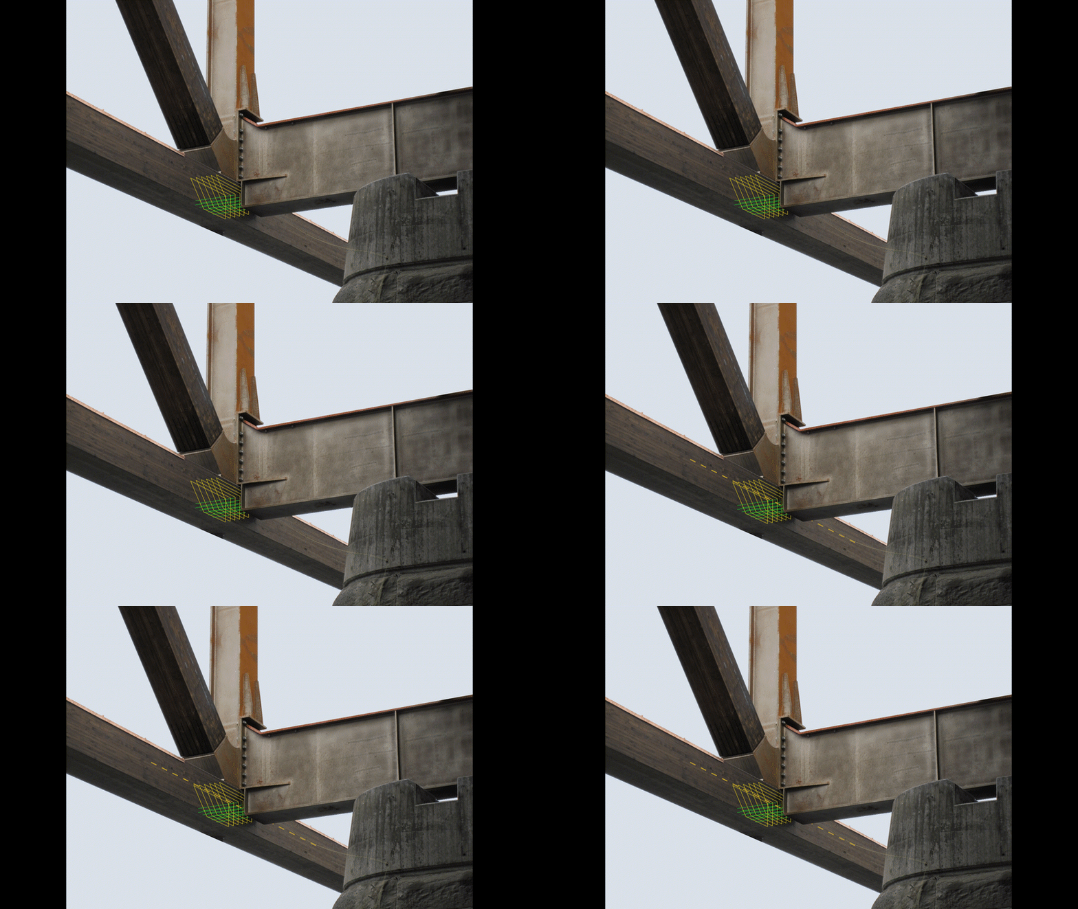
An animation depicting the freedom of movement I see at node 13 when a load is applied to the west span (I did not include any downward deflection of the lower chord). The crossbeam is not fixed to the stone support nor is it fixed to the road deck, therefore any horizontal load coming down the diagonal is only resisted by the pin array (2 rows of 5 pins). If the slots for the plates are oversized, there would not be any resistance (nor splitting action) contributed by the plates. The lower chord is fixed longitudinally by the east end of the structure.
Nine meter portion of bottom half of split lower chord recovered 15 km downstream:
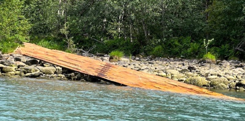

Nine meter portion of bottom half of split lower chord recovered 15 km downstream:

The suggestion that a simple tensile load applied to a connection caused the collapse would be tantamount to some sort of extraordinary negligence given the ease with which that mechanism could be studied and understood.
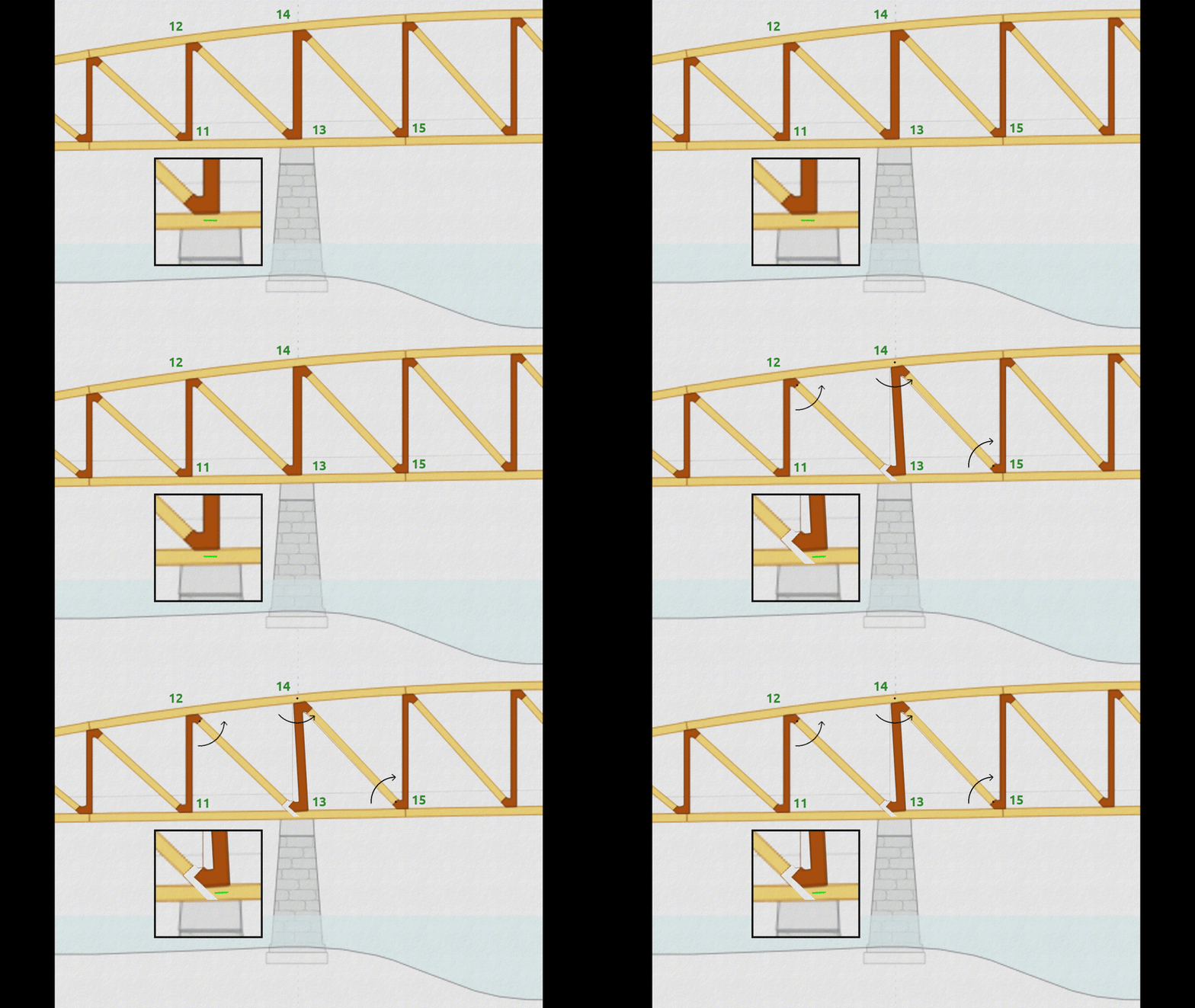
The new information is consistent with my theory (above at 21 Sep 22 01:38, 21 Sep 22 14:46, and 25 Sep 22 17:36) that the lower chord was split when load was applied to the west span. The knife like pin array at node 13 also rotates somewhat, amplifying its prying/splitting action on the lower chord. Again, the lower chord is unconventionally hung off the bottom of the vertical element and the steel frame is not constrained horizontally. It is the rotation of the diagonal between nodes 14 and 15 coupled with its tensile load that could push the connection at node 15 beyond its capacity. The greater catastrophe may be seen as a node 15 failure but the initiation may be an engineering failure at node 13.
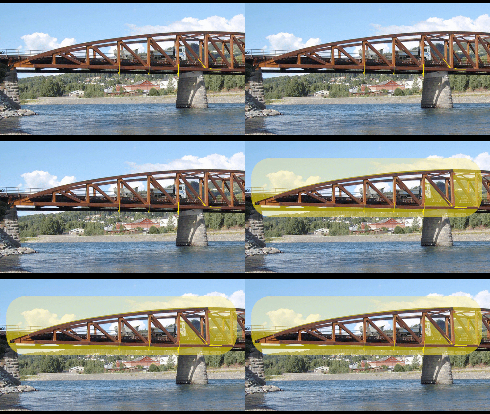
The photo of node 15 shows pins connecting the diagonal are bent in a manner consistent with this theory. None of the other connections show bent pins, let alone to this extreme.
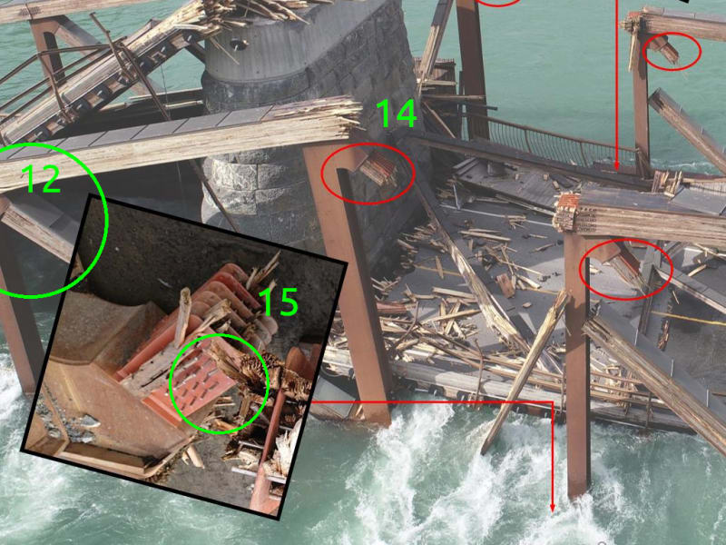
P.S. If the lorry was able to set the support vertical (13-14) to a three degree displacement (as the new animation depicts) prior to moving on to the center span, that would be the recipe for the ensuing disaster since it would put the 14-15 diagonal out of alignment prior to taking the load of the lorry.
The new information is consistent with my theory (above at 21 Sep 22 01:38, 21 Sep 22 14:46, and 25 Sep 22 17:36) that the lower chord was split when load was applied to the west span. The knife like pin array at node 13 also rotates somewhat, amplifying its prying/splitting action on the lower chord. Again, the lower chord is unconventionally hung off the bottom of the vertical element and the steel frame is not constrained horizontally. It is the rotation of the diagonal between nodes 14 and 15 coupled with its tensile load that could push the connection at node 15 beyond its capacity. The greater catastrophe may be seen as a node 15 failure but the initiation may be an engineering failure at node 13.


The photo of node 15 shows pins connecting the diagonal are bent in a manner consistent with this theory. None of the other connections show bent pins, let alone to this extreme.

P.S. If the lorry was able to set the support vertical (13-14) to a three degree displacement (as the new animation depicts) prior to moving on to the center span, that would be the recipe for the ensuing disaster since it would put the 14-15 diagonal out of alignment prior to taking the load of the lorry.
- Status
- Not open for further replies.
Similar threads
- Replies
- 13
- Views
- 13K
- Replies
- 17
- Views
- 11K
- Replies
- 33
- Views
- 3K
- Replies
- 1
- Views
- 852
- Locked
- Question
- Replies
- 1
- Views
- 2K
