Continue to Site

Eng-Tips is the largest engineering community on the Internet

Intelligent Work Forums for Engineering Professionals

  • Congratulations cowski on being selected by the Eng-Tips community for having the most helpful posts in the forums last week. Way to Go!

Orientation of a center plane of a tapered feature 2

Status
Not open for further replies.

Burunduk

Mechanical
May 2, 2019
2,513
A designer applied perpendicularity feature control frame with the leader pointing to a centerline representing the center plane of an internal taper feature (a "pocket" with symmetrical non-parallel opposed surfaces). I don't consider this specification valid according to ASME Y14.5-2009 but I'm struggling to provide a good explanation of why perpendicularity shouldn't be used this way. The one use of perpendicularity I know when it is applied on a virtual, derived geometry (as opposed to an actual surface) is when a center plane/axis of a feature of size is controlled. It doesn't seem right in the context of a tapered feature, not associated with a size dimension - but I can't form a good argument why. A valid point is that a center plane can be derived from a tapered feature (for example, a datum plane derived from tapered datum feature), and I suppose that a way to evaluate the derived plane orientation relative to a DRF can be found. I need your help, please.
 
Replies continue below

Recommended for you

chez311,
The relation of tolerance zones to true profile according to the chapter 8 quotations you provided is only defined for features specified with basic dimensions (or other methods such as model-based definition etc.). I have to correct my previous statement and say that true profile can be thought of as a boundary, but only in the cases of unilateral profile specification all outside/inside. By the way, true profile doesn't have to be constrained to DRF, for profile callout without DRF tolerance zones can be best-fitted relative to an unconstrained true profile. features can be best fitted into tolerance zones distributed around an unconstrained true profile.

Consider fig. 8-17. You can replace +/- tolerance on the base diameter with a basic one if you wish, I suppose it would make it less controversial. Is there no defined outer boundary? The fact that the diameter is located 0 to the base shouldn't bother. The base is considered a separate feature but it is really another circular element of the cone, not that different from the cross-sections except it's the circular element that "starts" the feature, so really the cone is located relative to itself. The base is fixed to the cone. Also, the fact that size is defined differently than for a cylinder or sphere, doesn't mean that it's not defined at all.

The only problem with MMB for a conical feature is that you can't prepare a fixed gage datum feature simulator for a primary datum feature MMB, it will just work as an RMB fixture. But, this doesn't really matter for UAME simulation for a conical feature because as I mentioned, amounts of offset from any boundary don't provide any useful data and directions of progression are interchangeable.

chez311 said:
Is everything except a planar feature a FOS?

No, curved open surfaces are not, a less than 180° arc is not.
 
pylfrm,

I'm trying to reconcile why unlimited offset from a basically defined true profile (conical feature with basic angle) would violate your definition of containment and unlimited offset from a non-basically defined true profile (cylindrical feature with +/-diameter) due to the fact that the size/dimension of the true profile is unspecified without limit wouldn't. It makes sense to me intuitively but I'm struggling analytically - perhaps it doesn't matter because the offset envelope itself (and perhaps not the amount/distance of offset) has a maximum/minimum in the latter case? But then we would have to define "maximum/minimum offset" in terms other than the amount (linear distance) of offset normal to the true profile. I'm sort of hunting to connect these two sides (basic vs. non-basically defined true profile) and I feel like I'm falling short.

https://www.eng-tips.com/viewthread.cfm?qid=448819)[/URL]]Unrelated actual mating envelope: A theoretical envelope outside the material, uniformly offset from a feature's true profile as far as possible in the direction toward the material. The relationship between the true profile and the actual surface is otherwise unconstrained. If the material of the feature does not provide a limit to the offset, no unrelated actual mating envelope exists.
 
Burunduk

I generally agree with your posted positions and logic. (Thread is so long I haven't read in great detail).
I find no reason to believe you are "confused" as previously posted in this thread. Your posts apply logic and present reasonable questions.
Just because one doesn't agree with another's "opinion" or interpretation, does not mean you are confused or incorrect.

The fact is that a discussion regarding a relatively simple "wedge" shaped feature was considered for dimensioning to reflect it's center plane and application of
a perpendicularity control. Just recapping in a general sense.

This is a finite physical feature which it and similar types have been designed with dimensions and tolerances, manufactured, inspected and functioned; multitudes of times.

"Infinity", "the standard is incorrect", "improperly defined", "unfortunately uses" are all useless in advancing the application of dimensioning and tolerancing to finite features and
parts. ASME Y14.5 2009 is the governing standard, its not perfect however it is what we have.

There is no doubt that a UAME according to the definition of ASME Y 14.5 2009 exists for the OP description. You stated your inspection department created one.

1.3.26.1 Unrelated Actual Minimum Material Envelope. said:
unrelated actual minimum material envelope: a
similar perfect feature(s) counterpart contracted about
an internal feature(s) or expanded within an external
feature(s), and not constrained to any datum reference
frame. See Fig. 1-2.

Screw threads are features of size. Tolerances of location are commonly applied to these complex features.
As I asked before, what is the UAME of a thread ? Default for thread for Tolerance of Location is the pitch cylinder ? Where is the UAME of the theoretical pitch cylinder ?

7.2 POSITIONAL TOLERANCING said:
Position is the location of one or more features of size
relative to one another or to one or more datums. A positional
tolerance defines either of the following:
(a) a zone within which the center, axis, or center
plane of a feature of size is permitted to vary from a true
(post comment: BTW location of tolerance zone)
(theoretically exact) position

A True Profile is not a boundary. Not in the definitions of ASME Y14.5 2009 Not once is "boundary" used for definition of a profile
8.2 PROFILE said:
A profile is an outline of a surface, a shape made up
of one or more features
, or a two-dimensional element
of one or more features
.

A tolerance in combination with a "true profile" defines a boundary
8.2.2 Profile Specification said:
The profile tolerance zone specifies a uniform
or nonuniform tolerance boundary along the true profile

within which the surface or single elements of the
surface must lie.

There is so much more that was posted and can be refuted, however I believe it wouldn't benefit anyone to do so.
 
dtmbuz,
I appreciate your support.
I took no offense over "confused", it was a reference to my own words about myself after trying to understand one of the figures posted in this thread. [smile]
I find it beneficial to discuss subjects with people that have different perspectives than my own, this helps to understand concepts better, and I appreciate all contributions and everyone who takes the time and effort to share their insight.

I have always had my own misgivings about tapered features - as I find that the Y14.5 standard text and examples provide very little information that can directly be referenced for dealing with them as with FOS. As you mentioned there is no shortage of practical methods, my own example of the "wedge gage" included, but there seems to be a lack of standardized and easily interpretable ways to apply FOS controls and FOS datum feature symbols to them.

Your example of the thread pitch cylinder is also very interesting. How does one "contain" a pitch cylinder by a UAME simulator? Doesn't seem to have enough coverage in the Y14.5 standard but for sure being dealt with a lot in the industry.
 
dtimbiz,

I'm sort of baffled and disheartened by your outright dismissal of the other side of the discussion. I had originally prepared a much longer response, but I'm going to try my best and keep it to a few points.

dtmbiz said:
There is no doubt that a UAME according to the definition of ASME Y 14.5 2009 exists for the OP description. You stated your inspection department created one.

That reasoning is sort of reductive isn't it? "someone did (x) therefore it must be correct". I never said extracting an axis from a cone is not possible, or that it can't be simulated - I just said that such simulation is not a UAME and such a feature is not a FOS.

dtmbiz said:
I find no reason to believe you are "confused" as previously posted in this thread.
dtmbiz said:
"the standard is incorrect", "improperly defined"

If you were referring to me, I never said these things.

chez311 said:
I think may be one of the most poorly, ambiguously, and frustratingly defined terms in the whole standard

The standard includes some terms and concepts which are either not defined or poorly/ambiguously defined to the point where they can be interpreted 100 different ways by 100 different people. My statement was voicing my frustration at such ambiguity. I typically strive to arrive at an unambiguous definition for some of these topics - I don't see how that is useless.

The standard is an imperfect document created by imperfect people. There are outright mistakes that have been found, however I was not discussing any in this particular thread.

Through this and other conversations we as a community attempt to dissect and understand some of the deeper concepts in the applicable standards. Sometimes that requires reading between the lines and possibly coming up with more creative or generally applicable definitions/interpretations. I happen to agree with the definition/interpretation put forth by pylfrm - Burunduk does not. Initially I only referenced that thread as in "hey this might be interesting - check it out". We proceeded to discuss the merits of said interpretation. If it got a bit heated I apologize, my frustration may have shown through a bit in my responses. If at any point they had said "I subscribe to a literal interpretation of the body of the standard and have no use for anything outside the exact words contained in the text" or something similar then the conversation would have ended. This was not was not stated and so we continued.


Also I don't understand the fixation on my statement about true profile as a "boundary". I already said call it whatever you wish, nothing in the sections you quoted - nor whether it is or isn't a boundary refutes anything I said prior. The use of the term boundary was clearly a poor choice - call it theoretical shape, profile, whatever - it makes no difference.
 
The relation of tolerance zones to true profile according to the chapter 8 quotations you provided is only defined for features specified with basic dimensions

If you take a literal reading of the standard then yes, you are correct. I happen to agree with pylfrm that adaptation of the concept of true profile to features of both basic and non-basic definition is useful in instances such as these.

HOWEVER - if we are referring to a conical/tapered profile defined with a basic angle then true profile per the text of the standard would certainly be applicable in this case.

By the way, true profile doesn't have to be constrained to DRF, for profile callout without DRF tolerance zones can be best-fitted relative to an unconstrained true profile.

Of course. You said a true profile "has no defined location in space relative to part, simulator, etc" and I was addressing that. If your FCF is datumless (which is obviously allowed) then there is no location/orientation constraint on the true profile and therefore the tolerance zone. I didn't think that had to be stated.

The fact that the diameter is located 0 to the base shouldn't bother. The base is considered a separate feature but it is really another circular element of the cone, not that different from the cross-sections except it's the circular element that "starts" the feature, so really the cone is located relative to itself. The base is fixed to the cone.

The base is truly a separate feature - they intersect at a point/edge yes but that is the limit to their interaction. They are no more part of the same feature than any other two features which intersect - say two sides of a square which meet at a corner. Either the cone is located relative to the base or the base is located relative to the cone. The cone is not located relative to itself - the exception being if the profile tolerance encompassed both the flat base and conical surface.

No, curved open surfaces are not, a less than 180° arc is not.

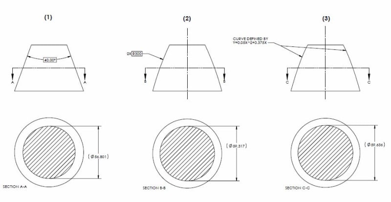
Yes I agree but I am interested why you think so. See below for three different features which I think satisfy your aforementioned requirements. All have circular cross sections - none of which I believe to be FOS. (2) and (3) would behave similarly to a conical feature (1) on a simulator namely "As long as it's set, it contains/being contained".

Note (2) has two opposed circular arcs - I did not include a dimension between the centers as they are 500mm apart.

round_and_parabolic_nonFOS_az0ax9.jpg
 
chez311 said:
I happen to agree with pylfrm that adaptation of the concept of true profile to features of both basic and non-basic definition is useful in instances such as these.

HOWEVER - if we are referring to a conical/tapered profile defined with a basic angle then true profile per the text of the standard would certainly be applicable in this case.

In the thread opened by dtmbiz, I explained further the source of my misunderstanding of the relation of true profile "per the text of the standard" to conical AME simulation, and the related "unlimited offset" issue. It isn't desired that the true profile related discussion drags into that thread so I will repost the relevant part of it here and I would appreciate if you can address this:

Burunduk said:
To be exact, the main argument against tapered features being features of size was the "unlimited offset" from the true profile to the unrelated actual mating envelope simulator during the simulation process, as was shown in this illustration ... for me, there are still open questions: What does the "true profile" do in that process? This is not a tolerance validation process, but a process intended to derive an axis from a considered feature, i.e. performed prior to tolerance validation that requires anything "true" (true position or true orientation may be more relevant anyway, but then how does the shown offset matter?) And if "true profile" is already there, why doesn't it follow the feature and/or the envelope simulator? Been looking for clues in the standard to no avail.

I think I now realize that the unlimited offset scenario is based explicitly on the definition suggested by pylfrm: "...uniformly offset from a feature's true profile as far as possible in the direction toward the material." I realize you do not wish to take the standard's definition literally, but even so, we already agreed that the true profile is not some boundary outside or inside the material, it is merely the theoretical exact form of the feature, so where is it relative to the actual feature, to begin with? Without knowing this, there is no basis for talking about normal offset towards the material of the feature and assume it should eventually bring the simulator to contain the feature. When I claimed, based on my understanding of the non-literal interpretation of true profile you and pylfrm suggested, that true profile has no defined location or orientation relative to the actual feature, your response was a reference to para. 8.2: "Profile tolerances are used to define a tolerance zone to control form or combinations of size, form, orientation, and location of a feature(s) relative to a true profile." So:
1. Are we dealing with the literal or the non-literal interpretation?
2. If the relationship between the feature and the true profile is based on the true profile being the foundation of tolerance zones to which the feature surface is validated, how does it end up being infinitely offset from the feature under any circumstances?
3. Finally, how is true profile which is a tolerance zones "carrier" for a surface control is even remotely related to UAME - axis derivation?

chez311 said:
The base is truly a separate feature - they intersect at a point/edge yes but that is the limit to their interaction

Yes, but that doesn't make the theoretical envelope that constitutes the unrelated actual mating envelope any less "unrelated", the base doesn't act as a datum feature and doesn't constrain the envelope, not in orientation, and certainly not in location, so I don't see where the problem is.

Regarding the 3 figures at the end of your post, I don't see why any of them can't be contained by a potential UAME simulator of the exact inverse theoretical form of the feature, edit: except for the one reservation I already mentioned several times - the requirement for adjustable size of the datum feature simulator.
 
your response was a reference to para. 8.2

I see I may have fired that one off before thinking about it enough. We were talking about establishing a UAME therefore it would indeed be unconstrained in location/orientation. I think some wires may have gotten crossed there.

I realize you do not wish to take the standard's definition literally, but even so, we already agreed that the true profile is not some boundary outside or inside the material, it is merely the theoretical exact form of the feature, so where is it relative to the actual feature, to begin with? Without knowing this, there is no basis for talking about normal offset towards the material of the feature and assume it should eventually bring the simulator to contain the feature.

(...)

1. Are we dealing with the literal or the non-literal interpretation?
2. If the relationship between the feature and the true profile is based on the true profile being the foundation of tolerance zones to which the feature surface is validated, how does it end up being infinitely offset from the feature under any circumstances?
3. Finally, how is true profile which is a tolerance zones "carrier" for a surface control is even remotely related to UAME - axis derivation?

1. I don't think the interpretations of true profile itself are any different, its the application of the true profile to the definition of UAME that is beyond the definition provided by the standard.
2. I think I see what you're getting at here - I'm not sure I can satisfactorily answer this. I'm hoping pylfrm can perhaps help clarify this a bit.
3. If we can derive an axis from the UAME then it is because we can derive an axis from the true profile. I would say they are related because they are the same axis.

In relation to your (2.) and the preceding quoted statement about the true profile and "where is it relative to the actual feature" - I think we need some more clarification from pylfrm as to how this relationship should look. I thought I had a good grasp on it, but I realize now my understanding may have had some gaps.

Yes, but that doesn't make the theoretical envelope that constitutes the unrelated actual mating envelope any less "unrelated", the base doesn't act as a datum feature and doesn't constrain the envelope, not in orientation, and certainly not in location, so I don't see where the problem is.

Per the bolded, it does in the situations you stated as being examples of being able to establish an MMB. See my (a), (b), and (c) in my response (20 Nov 19 15:22) - all three of these have location specifications (+/- toleranced or basic) between the base and the tapered portion. My point is that these aren't really "size" per se but location which is why I said that "size of a conical/tapered feature only matters in relation to something else" - without these location specifications an MMB is not defined for a conical/tapered feature, for example 8-18 without the basic 18 dimension. The caveat being that the conical/tapered portion would have to be specified as secondary or lower precedence with said location constraints - if specified as a primary datum feature it would still have no MMB as it would no longer be location constrained.
 
pylfrm,

I am hoping you could help me reconcile these two concepts per my (21 Nov 19 07:01) as well as perhaps help me (us?) understand what sort of behavior your intended from a UAME defined from a feature's true profile per Burunduk's #2 question in the post on (25 Nov 19 19:48). I thought I understood your reasoning however it appears I may have some gaps in my understanding. Perhaps a figure or graphic of the intended relative location of the true profile vs. part surface vs. UAME boundary and how the offset of the UAME boundary would occur?

Thanks as always for your help, I still believe in the logic of your extension of concept I just need some help filling in the gaps.
 
chez311, I generally follow your logic about the size of a tapered feature being location dependent, although I still wouldn't relate this type of dependency to DOF constraints as imposed by datum features. Further on this:

chez311 said:
without these location specifications an MMB is not defined for a conical/tapered feature, for example 8-18 without the basic 18 dimension. The caveat being that the conical/tapered portion would have to be specified as secondary or lower precedence with said location constraints - if specified as a primary datum feature it would still have no MMB as it would no longer be location constrained.

Fig. 2-19 shows a feature of similar geometry, specified with only directly toleranced dimensions and no datum features involved, therefore there are no constraints of degrees of freedom. Do you think that in this case too the conical feature cannot be specified as a primary datum feature? And, has no MMB?

 
And regarding the true profile:
chez311 said:
3. If we can derive an axis from the UAME then it is because we can derive an axis from the true profile. I would say they are related because they are the same axis.

That is why I thought that the "true profile" in the conical (potential) UAME simulation should stay coincident with the (potential) UAME simulator, not accumulating any offset. In this case, I think the simulator also represents the "true profile" - it is the same theoretical geometry (from which the axis is derived).
 
Do you think that in this case too the conical feature cannot be specified as a primary datum feature? And, has no MMB?

I didn't mean to suggest that. A conical feature may be specified as a primary datum feature without issue - however it will not have an MMB, same as a planar feature referenced as a primary datum feature.

That is why I thought that the "true profile" in the conical (potential) UAME simulation should stay coincident with the (potential) UAME simulator, not accumulating any offset. In this case, I think the simulator also represents the "true profile" - it is the same theoretical geometry (from which the axis is derived).

I see no reason why that must be the case. Imagine a cylindrical feature specified with a basic diameter. The true profile would be defined by the basic diameter and the UAME may expand/contract ie: uniformly offset from the true profile, while sharing the same axis. Perhaps instead of saying they are the same axis, we could say they have coincident axes - I don't think it changes much.

So too would a conical boundary be uniformly offset from the true profile while sharing (or having coincident) axes.
 
chez311 said:
I see no reason why that must be the case. Imagine a cylindrical feature specified with a basic diameter.
Notice that I wrote "in this case" meaning a conical feature specifically. I understand and accept (per the non-standard use of the true profile term) "uniform offset from true profile" of a UAME simulator of a cylindrical feature as it expands or contracts. I do not understand "uniform offset from true profile" for a conical simulator. For me, it makes as much sense as talking about "uniform offset from true profile" for a planar datum feature simulator and claiming it may become "unlimited" during a simulation. That is notwithstanding the fact that a conical and plane feature are two completely different features, and the former still can potentially be a FOS in my opinion.
 
ASME Y14.5-2009 datum feature references without MMB or LMB or other modifiers can behave in a few fundamentally different ways.

One type of behavior is that which is explicitly specified with the [BSC] or [BASIC] modifier as shown in Fig. 4-28 and Fig. 4-31(b). Here the datum feature simulator coincides with the true profile of the surface. Examples of this where the datum feature is a planar surface include D, E, and F in Fig. 4-2 and A, B, and C in Fig. 4-7. Other examples include A-B in Fig. 4-22 where the datum feature is a pair of non-opposed planar surfaces, and A in Fig. 4-44 where the datum feature is a conical surface.

A second type of behavior is where the datum feature simulator expands or contracts (or does something analogous) toward the datum feature until contact with the feature stops it. Examples of this where the datum feature is one complete cylindrical surface or a pair of opposed planar surfaces include B and D in Fig. 4-4; B and C in Fig. 4-9; and B and C in Fig. 4-15. Other examples include B in Fig. 4-29 where the datum feature is a partial cylindrical surface, and B in Fig. 4-30 where the datum feature is a planar surface. If the position tolerance in Fig. 4-45 referenced [box]B[/box][box]A[/box] instead of [box]A [x,y,u,v][/box][box]B [z][/box], then the conical surface B would be an example if this as well.

I'd say this second type of behavior involves the defining characteristics of an AME, or UAME in the special case of a primary datum feature reference. The first type of behavior does not involve these characteristics, but it's the only viable option for a conical primary datum feature reference.

I realize this is not a direct answer to the questions asked, but hopefully it will help explain how I view this without straying too far from the standard.


perhaps it doesn't matter because the offset envelope itself (and perhaps not the amount/distance of offset) has a maximum/minimum in the latter case?

Yes, this is what I have in mind.


But then we would have to define "maximum/minimum offset" in terms other than the amount (linear distance) of offset normal to the true profile.

Agreed. A useful analogy might be the determination of the highest point on the surface of the earth. If you can compare any two points and decide which is higher, then there is no need to worry about the actual elevation of any point relative to sea level.


Fig. 2-19 shows a feature of similar geometry, specified with only directly toleranced dimensions and no datum features involved, therefore there are no constraints of degrees of freedom. Do you think that in this case too the conical feature cannot be specified as a primary datum feature? And, has no MMB?

I'd say that the meaning of a datum feature reference to that surface would be undefined due to insufficient specification of its basic geometry. I'd also say that is has no meaningful MMB in the "unrelated" sense.


I do not understand "uniform offset from true profile" for a conical simulator. For me, it makes as much sense as talking about "uniform offset from true profile" for a planar datum feature simulator and claiming it may become "unlimited" during a simulation.

The point is that planar primary datum feature references don't behave in that nonsensical way, and neither do conical primary datum feature references.


pylfrm
 
pylfrm said:
The point is that planar primary datum feature references don't behave in that nonsensical way, and neither do conical primary datum feature references.

pylfrm, If I make the right conclusion out of this, it seems that we should have been discussing RAME simulation, not UAME.
Is that correct? All the examples you referred to where the simulator should progress normal to the true profile are related to secondary datum feature simulation. It seems like after all there is little, if any, meaning to offset from true profile for a simulator unconstrained to any datums. Reconnecting this to the FOS/non-FOS subject, should the main question be whether a tapered feature can constrain the simulator of the related actual mating envelope when it is prescribed to behave as in the "second type of behavior" you described above?
 
I don't see why they need to be mutually exclusive. Thats the beauty of the interpretation utilizing uniform offset from the true profile - it can be applied to literally any shape. This in includes a single planar feature.

For me, it makes as much sense as talking about "uniform offset from true profile" for a planar datum feature simulator and claiming it may become "unlimited" during a simulation. That is notwithstanding the fact that a conical and plane feature are two completely different features, and the former still can potentially be a FOS in my opinion.

Per my above (and I think I've mentioned it before), I don't see any reason why the uniform offset from the true profile of a planar feature couldn't be discussed. It would behave in a similar manner to a conical feature - and would be declared a nonFOS for the same reasons. As pylfrm postulated in the originally referenced thread, do you not see some strong similarities of a conical feature having 179deg included angle and a planar feature? In fact I think an argument could be made that the distinction between a planar feature and a conical/tapered feature having 180deg included angle is more philosophical than mathematic - geometrically the two are indistinguishable.
 
pylfrm,

To echo Burunduk, did you mean to include only examples exhibiting a RAME in your second type of behavior? I originally took it too mean that your concept of "uniform offset from the true profile" could be applied in cases both where the true profile is unconstrained (UAME) and constrained (RAME).

I think I mostly understand what you mean though by outlining the two different types of behavior, correct me if I'm wrong but putting it into simple terms if we are to compare two internal features that are cylindrical and conical - the behavior which allows expansion of a cylindrical simulator until it reaches a maximum limited by the feature (envelope offset from the true profile) is fundamentally different than the ability to set a conical feature on a conical simulator (envelope coincident with the true profile). The takeaway being that the former behavior is required for UAME simulation.

As far as the actual behavior of the true profile compared to the uniform offset of the true profile, I think I've mostly worked through it however I wanted to directly address Burunduk's question that planted a seed of doubt in my mind:
If the relationship between the feature and the true profile is based on the true profile being the foundation of tolerance zones to which the feature surface is validated, how does it end up being infinitely offset from the feature under any circumstances?

My guess is that the true profile which you refer to is the same as in it is defined by the same geometry but it is not necessarily coincident with the true profile which defines the tolerance zone to which the feature conforms - otherwise as Burunduk noted unlimited offset would not be possible as both the true profile (about which the tolerance zone is disposed) and the feature would have to remain within the tolerance zone and therefore so too would the envelope which is uniformly offset from the true profile in the direction of the feature.

I'm glad I was on somewhat of the right track with the "unspecified offset" of a non basically defined true profile. I don't think thats quite the satisfying conclusion I had hoped, but it does help.
 
pylfrm, If I make the right conclusion out of this, it seems that we should have been discussing RAME simulation, not UAME.
Is that correct? All the examples you referred to where the simulator should progress normal to the true profile are related to secondary datum feature simulation. It seems like after all there is little, if any, meaning to offset from true profile for a simulator unconstrained to any datums.

I disagree. I should have included some primary datum feature references in my list. One example with a fully-defined true profile is A in Fig. 4-34. If you're willing to consider cases without a fully-defined true profile, then another example is A in Fig. 4-29. Of course it would be easy to transform that into something less controversial by changing the 40 +/- 0.1 dimension to basic.


Reconnecting this to the FOS/non-FOS subject, should the main question be whether a tapered feature can constrain the simulator of the related actual mating envelope when it is prescribed to behave as in the "second type of behavior" you described above?

Although it's not explicitly stated, I think the actual mating envelope that's relevant to the definition of 'irregular feature of size' is the unrelated one. Higher-precedence datum feature references would need to be involved for a related actual mating envelope, and different choices of those would lead to different answers. I don't think that would make much sense.


the behavior which allows expansion of a cylindrical simulator until it reaches a maximum limited by the feature (envelope offset from the true profile) is fundamentally different than the ability to set a conical feature on a conical simulator (envelope coincident with the true profile). The takeaway being that the former behavior is required for UAME simulation.

Agreed.


If the relationship between the feature and the true profile is based on the true profile being the foundation of tolerance zones to which the feature surface is validated, how does it end up being infinitely offset from the feature under any circumstances?

My guess is that the true profile which you refer to is the same as in it is defined by the same geometry but it is not necessarily coincident with the true profile which defines the tolerance zone to which the feature conforms

Yes. The relationship between the actual part and the basic geometry may be different because different datum feature references (or lack thereof) are involved. I recall a good example of this in thread1103-444710.

In general, determination of a feature's UAME (if it exists) or RAME(s) doesn't have anything to do with the tolerances that are (or are not) applied to that feature.


pylfrm
 
chez311 said:
I don't see any reason why the uniform offset from the true profile of a planar feature couldn't be discussed.

Then let's discuss it. A conical simulator for a secondary datum feature will probably need to expand or contract or progress from MMB to LMB (for external feature) in a way equivalent to how it is shown in fig. 4-31 illustration (a) for a planar feature, which in my opinion could be added to the examples of "the second type of behavior" by pylfrm. If for the part in that figure we would rely on the ability of the actual feature to limit the movement of the simulator, then there too unlimited offset of the simulator from its initial position would occur, as the part would rotate around the primary axis. Instead, there are two restrictions imposed by the standard:

1. The range of translation of the simulator is pre-limited from the MMB to the LMB, there would be no purpose in crossing these limits - don't see why this can't also be the case for a secondary conical datum feature (this echoes my previous attempts to convey the need in replacing "true profile" with MMB as the origin of the offset in question). Regarding MMB my assertion is that for any closed surface (including conical) defined with basic dimensions and a profile tolerance a maximum material boundary exists (I.e. outer boundary for an external feature). This alone already makes "unlimited offset" impossible.

2. The simulation is required to stop when "maximum possible contact" is made. I don't like the concept of maximum possible contact either - if the surface of datum feature B is produced as a convex arc (within its planar profile tolerance range) then maximum possible contact is pretty much ambiguous. But, this is what the standard we work by prescribes, and - for a conical simulator I would say "maximum possible contact" or a term I personally would prefer - stable contact is less ambiguous than in the planar case, because of the centering and effect of cone-to-cone interaction. This further rejects any type of "unlimited offset" during simulation.
 
pylfrm said:
I disagree. I should have included some primary datum feature references in my list...

... Although it's not explicitly stated, I think the actual mating envelope that's relevant to the definition of 'irregular feature of size' is the unrelated one

Then, if it is still the primary datum feature simulation / UAME simulation under question, it seems that "unlimited offset" issue is eliminated in that regard:

pylfrm 3 Dec 19 05:39 said:
Burunduk said:
I do not understand "uniform offset from true profile" for a conical simulator. For me, it makes as much sense as talking about "uniform offset from true profile" for a planar datum feature simulator and claiming it may become "unlimited" during a simulation.

The point is that planar primary datum feature references don't behave in that nonsensical way, and neither do conical primary datum feature references.

Per the above, for a conical feature, there is no issue with the simulation of the type of AME that defines an irregular feature of size.

 
Status
Not open for further replies.

Part and Inventory Search

Sponsor