Continue to Site

Eng-Tips is the largest engineering community on the Internet

Intelligent Work Forums for Engineering Professionals

  • Congratulations waross on being selected by the Eng-Tips community for having the most helpful posts in the forums last week. Way to Go!

Overhead sign crushes car on freeway in Melbourne Australia. 3

Status
Not open for further replies.

MDEAus

Mechanical
Mar 21, 2018
44
This happened a few days ago, but the article has just been updated with dash-cam footage from the car immediately behind the one involved.
very quickly it can be seen that the failure point is at the welded joint for the bolted connection. the grainy footage makes things harder to see, the base off the standoff looks weird, why would you close the end off the SHS to be welded to the main beam? Galvanising requires drainage points and a minimum area open between closed sections. Unless that is a solid block off steel? I'm not sure why they would have used a solid block off steel though.

 
Replies continue below

Recommended for you

I read it that only 3 required the stiffener by design. I wonder if the detailing of the stiffener would have prevented the failure. A single central stiffener for example would really align with the stubs flanges for example.

I wonder how it was called up on drawings and how it was apparently easily missed 3 times. I bet there's a lesson to be learned there.
 
Sounds like there were 17 total similar gantries, but only 3 of them were supporting large cantilevered signs that required the base connection to be stiffened. Either it was missed that they were required in the fabrication and none of them included stiffeners, or perhaps several of the gantries were too similar and there are 3 out there with stiffeners, but they were installed in other locations. It's also possible that the other 2 that needed stiffeners actually do have them, but they have to get inside them to find out.
 
I can't see the stiffeners being installed inside. I visualize a stiffener plate thick enough that the welded stub will not break free and with a large enough perimeter that the weld from the stiffener to the gantry will not fatigue.

Bill
--------------------
"Why not the best?"
Jimmy Carter
 
I also saw the newspaper article to which dgallup refers.[ ] As I read the sentence he quotes I was immediately struck by its beautiful ambiguity, and wondered whether the credit belonged to Clements or the reporter.[ ] (Probably the reporter?)
 
If the story rapt linked to was accurate, the stiffeners were inside and not visible, which is why no one realized they weren't there until it broke.
 
Yeah those two sentences are strange, but it reads like this. Out of the 17 similar signs left 3 had spec details for an internal stiffener; of those 3 gantries 2 were missing the spec'd stiffener. All three have had their signs removed for the investigation.

"Mr Clements said the stiffener plates were not visible to the naked eye and therefore could have been missed during the final inspection of the signs."

If something won't be visible on the final inspection maybe it should be inspected at a time when it is still visible.

Denial,
Given that they are quotes I'd say the ambiguity comes from Mr Clements rather than the reporter.

It'd be interesting to get a copy of the drafts to see what the "internal stiffener" is.
 
Is it usual in Australia for most structures as the engineer to get shop drawings for review before anything is fabricated?

If so, the way I see it is that there are probably multiple steps in the process where both the engineer and fabricator could/should have noted the deficiency or lack of stiffeners?

1 - Engineers internal design verification process (assuming the stiffener was not noted on the drawings but designer was aware they were required)
2 - Shop detailer reading engineers drawings (assuming the stiffener was noted)
3 - Engineers review of shop drawings (assuming engineer had it on their drawings and shop detailer inadvertently missed it, or if it wasn't on the engineers drawings then the engineer realises the mistake and corrects it)
4 - Welding inspectors QA checks (assuming it was noted on the shop drawings)
5 - other...

The media insinuate a fabrication error, but it could equally be an engineering error.
 
I'm having trouble understanding how a stiffener on the inside would prevent those pieces of metal from being torn out of the gantry.
Can anyone help me here?

Bill
--------------------
"Why not the best?"
Jimmy Carter
 
If it has indeed torn out of the wall it's likely failed due to fatigue, in a way too much concentrated stress on parts of the wall of the girder and too many reversals of this stress from wind/traffic etc until it cracks, crack propagates under further loading until it fails completely, an appropriately designed and detailed stiffener would likely provide a more distributed load path for the forces in effect better distributing or eliminating the peaks in stress that contribute more cumulative damage to an eventual fatigue failure.
 
The stiffener could have been either gussets under each stub post or some plate on edge running the length of the gantry. It's goal would be to reduce the out of plane bending on the comparatively thin shell of the gantry (essentially acting like the web of an I beam). Or it could have been intended that a thick plate (20mm or greater) oversized around the stub post, I personally think this would be a terrible option; fatigue might still occur (at the same place) unless the skin is plug or spot welded to the thicker plate.

If the plate is large enough to avoid fatiguing at the stub post joint it would require plug or spot welding or the skin would still be able to pull away around the stub post joint.

This article doesn't add any new information but says the report is upto 8 weeks away.

 
Agree with some others that using stiffeners wholly inside a box member is fraught with danger. It just doesn't lead to effective control/inspection, even if the strength issues are addressed adequately.
 
HotRod10 said:
Sounds like there were 17 total similar gantries, but only 3 of them were supporting large cantilevered signs that required the base connection to be stiffened
Given the context that they removed signs from three gantries, I'd say the stiffener was shown on the design drawings for only those three gantries. But the quote also said 17 gantries with similar signs supported "in this manner". I hope they've asked the designer to confirm that 14 gantries didn't have the stiffeners deleted from the drawings by mistake. These things happen when copying drawings.

Agent666 said:
there are probably multiple steps in the process where both the engineer and fabricator could/should have noted the deficiency or lack of stiffeners?
1 - Engineers internal design verification process (assuming the stiffener was not noted on the drawings but designer was aware they were required)
2 - Shop detailer reading engineers drawings (assuming the stiffener was noted)
3 - Engineers review of shop drawings (assuming engineer had it on their drawings and shop detailer inadvertently missed it, or if it wasn't on the engineers drawings then the engineer realises the mistake and corrects it)
4 - Welding inspectors QA checks (assuming it was noted on the shop drawings)
5 - other...

I'd say it's likely that there was only one step when the mistake could have been noticed, but maybe two depending on where in the process the mistake entered.
 
Thank you for the explanations everyone.
I am sure that I am not the only one who has been wondering about this.
MDEAus said:
The stiffener could have been either gussets under each stub post or some plate on edge running the length of the gantry.
I hadn't thought of this.

Bill
--------------------
"Why not the best?"
Jimmy Carter
 
I would think the stiffener, to be most effective, would take the form of a vertical plate aligning with the edges of the stub post and extending down inside the box of the gantry. Best if it attached to all 4 sides of the box, but straight down to the bottom would be fairly effective. Stiffening the stub against fatigue requires preventing the back edge (the one opposite the front vertical face of the gantry) from moving, so that the top plate of the gantry doesn't flex out-of-plane (vertically) and fatigue. A longitudinal stiffener could be some what effective, but again, it would have to align with the interior edge of the stub post and extend a significant distance along the gantry to spread the load along the top plate of the gantry.

The simplest and most effective is a configuration that essentially extends the stub post down inside the gantry, or better yet, actually extending the 'stub post' through the gantry and weld it on the top and bottom. That's what I would have done, as it eliminates the the possibility of moisture getting trapped inside the post, makes all the welds visible, and gives you the connection to gantry with the least amount of stress and flexibility.
 
I was driving along the westgate freeway section of the M1 yesterday (not all that far away from where the sign fell) and noticed that two signs on a gantry had been removed and some white 'paint' applied at the top of the gantry that looked a lot like some NDE of welds had been occurring. The framework for the sign was all there, it was just the actual sign (large sheet) that had been removed.

I've seen similar gantries back in late 2017 painted the same colour at an industrial painter in Melbourne and I'm fairly sure the wall thickness was 8 to 10mm, though I can't be 100% sure I'm remembering the thickness correctly.

Here is a Link to what appears to be some of the research, including the FE methodology recommendations, that appears to have influenced the 2015 version of the AASHTO highway structural supports code.

I don't have the 2015 code only the 2009 code so I can't see what clause 5.6.2 states regarding SHS/RHS - if anyone could elaborate further that would be much appreciated.
 
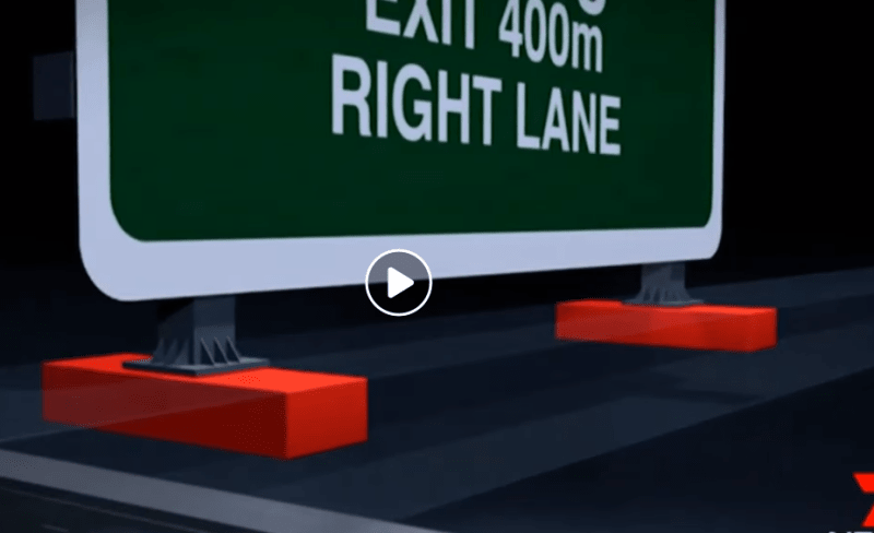
If that artists rendition of the stiffeners is anything to go by they may have been SHS/RHS running from front to back off the sign. I feel that would be less than optimal but probably would have been satisfactory. On second thoughts it's probably just a guess rather than any technical insight as the base off the sign isn't accurate at all.

shitty_render_ivtsbg.png
 
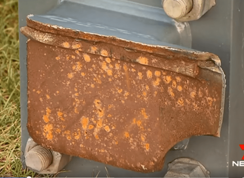
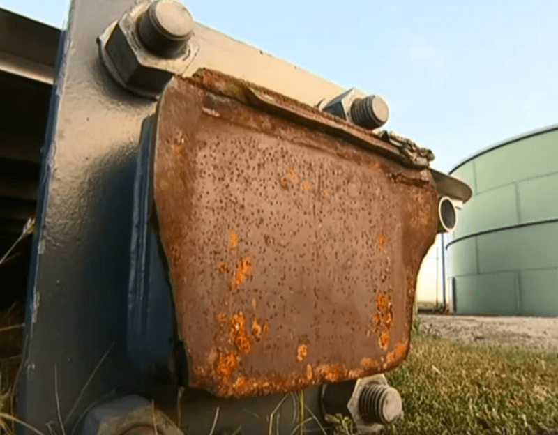
Looks to me like the stub was located on the front of the gantry fright over the weld to the built up section, you can see what looks like the return of the front wall in the 1st photo, and what looks like a backing plate at the junction.

I thought and could be wrong, but for fatigue shouldn't any backing plates be removed?? Wonder what AS/NZS1554.5 notes?

2nd photo doesn't seem to show any fusion into the backing plate, I feel this is a key point if it was supposed to have full penetration as suggested by the presence of a backing plate, with the root of the weld to the gantry potentially acting as a crack initiator?

Partial penetration butt weld wouldn't require a backing plate.

You can see what looks like some of the tack weld where backing plate was attached to the wall during fabrication in the 2nd photo, and the 'shadow' of where it was placed in the junction. Its probably still attached to the gantry!


Capture_tsgr38.png


Capture1_qh1sxj.png
 
How would you remove backing plates from inside the closed section?
 
Don't ask me!... like I said I'm not sure now having looked through AS/NZS1554.5. It just states for permanent backing left in place, that it needs to have a similar weldability.

Definitely if you look at the top backing plate there is weld fusion on the backing plate, but the bottom one really doesn't look like there was any, but could just be my eyes playing tricks on me.

Shame these pictures weren't taken directly after so you could see what might have potentially been older rusted cracks vs fresh fractures?


Status
Not open for further replies.

Part and Inventory Search

Sponsor