Continue to Site

Eng-Tips is the largest engineering community on the Internet

Intelligent Work Forums for Engineering Professionals

  • Congratulations waross on being selected by the Eng-Tips community for having the most helpful posts in the forums last week. Way to Go!

Position tolerance datums 3

PtoMonty

Mechanical
Sep 17, 2024
8
Hello all,

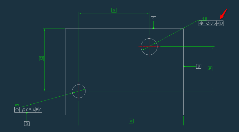
I have been trying to find an answer to this one and maybe you could give me your 2 cents. If I want to control the position of one hole in relation to another do you considered that I still need the 3 datums? Below I made a simplified drawing of what I consider to be a correct position tolerance for the hole in the top rigth. Am I till controlling all degrees of freedom? A is not in the picture but consider it as the plane defined by one of the faces perpendicular to the hole axis.

Thanks in advance.
2024-09-17_16h10_43_cdt3rt.png
 
Replies continue below

Recommended for you

PtoMonty,
Position relative to A,D will control only how perpendicular the hole can be relative to datum A and the distance from datum axis D derived from the bottom left hole. It will not control location relative to the rest of the part.
 
PtoMonty,

What is the function of the part? If you want to control the location of the 11 mm hole relative to the 9 mm hole, you'd likely be better off keeping your existing datum A and setting the axis of the 9 mm hole as datum B. Then you can control the location of the 11 mm hole without unnecessary tolerance stack up resulting from imperfections in your datum features B and C. This assumes that the location of the holes relative to each other is more important than the overall size of the part or form or orientation of the edges that make up datum features B and C.
 
PtoMonty, just an aside: you're not required to constrain all degrees of freedom. Only what's need for a particular callout.
 
Hi, PtoMonty:

Well, it is up to you how to refer your datum features in your FCF (feature control frames). If you just call out datum feature "A" and "D" as you did, then dia. 9mm hole is "fixed" like the Sun, while dia. 11 hole is "floating" like the Moon. Is that your design intent?

Best regards,

Alex
 
Even though I generally agree with Garland that not every geometric tolerance needs to lock all degrees of freedom, I would suggest being careful not to leave any degrees of freedom unlocked for a position tolerance that is not coaxial with the datum. This could result in an incomplete requirement.

However, sometimes you can get away with the default rules available in the ASME Y14.5 standard, such as simultaneous requirements that apply to multiple features and therefore tie them together, even when not all DOF are locked by the datum references in each of the feature control frames. For example, if the outer surfaces of the part are controlled by an all-around profile tolerance and also reference the same datums A and D, in that same order and with D Regardless Feature Size, the distances between the outer surface and the top-right hole will be under control.
 
Hello all,

Thanks for the answers. The sketch is just a simplification of the actual part. Both the relative location of the holes and it's position to the outer shape are important. THe reason why I want the 11 mm hole controlled in relation to the 9 mm one is that when assembled the 9 mm hole will be engaged first and only after the 11 mm hole. So the 9 mm hole will determine the position of this part to its mating part. The actual part has two 9 mm hole which engage simultaneously and control therefore rotation as well.

Replying to jassco, I want the 11 mm hole also fixed. Would referencing twice datum D make sense then? -> Pos|Dia 0.5|A|D|D
 
OP said:
The actual part has two 9 mm hole which engage simultaneously and control therefore rotation as well.
So for the actual part the best way to call out the datum might be to use the pattern of the two 9 mm holes as a single datum feature. In that case A primary (the large face) and D secondary (the two holes) will eventually constrain all 6 degrees of freedom.
 
Hi, PtoMonty:

No. Referencing "D" twice makes no sense.

If the two holes are equally important, then you need to position them to datum A|B|C. There are two ways to position them to datum A|B|C. You can independently position each hole to datum A|B|C, or as Burunduk suggested, you can position these holes as a pattern to A|B|C.

If the distance between these holes is critical to your application, then you will need datum feature "D". But you will need to control orientation of the hole (dia. 11). Otherwise, this hole would fly like the "Moon".

Do you use two dowel pins in your assembly? If you do, you may want to either make one of the pin as "diamond" shape or make the hole (dia. 11) as a slot. Otherwise, they would fight each other.

Best regards,

Alex
 
Hi, PtoMonty:

You mentioned that the actual part has two 9 mm holes. You can use these features below to locate dia. 11 holes.

Primary: A (bottom of the part);

Secondary:: One of the 9mm holes;

Tertiary: The other 9mm hole.

Alternatively, you can use these two datum features below:

Primary: A (bottom of the part);

Secondary:: Pattern of the two 9mm holes.

Then you can position 11mm holes to datum A|B (B as a pattern).

You can use profiles to control outer faces of the rectangle blocks in reference to datum A|B.

But keep in mind that the pattern of your two 9mm holes won't be a robust datum feature if they are too close to each other.

Best regards,

Alex
 
Alex said:
Alternatively, you can use these two datum features below:

Primary: A (bottom of the part);

Secondary:: Pattern of the two 9mm holes.

Then you can position 11mm holes to datum A|B (B as a pattern).

This is the solution I would choose, with the datum B reference at MMB (assuming the two 9 mm holes mate to two pins with non-adjustable diameter, and without a particular order). This is also what I meant by my previous response.

The patterm of the two 9 mm holes would also need to have a position control with reference to A, preferably at MMC for the mentioned assumed application.
 
The simplest is to depend on the simultaneous condition rule and position all the holes with the same datum references in the same order at the same conditions. This will remove tolerance stackup related problems. In this case all would reference [A].

The only reason not to is if a drill plate is used to located the 11mm hole from expanding gage pins installed at the 9mm holes.

That will allow the most sloppy work to be accepted, though the expense of making that plate will increase the cost to locate the 11mm hole.

If the holes are put in on a mill in one setup, then they already have a simultaneous condition limited by the precision of the mill and care in sharpening the cutting tool. Alternatively, a drill plate with all three (or however many) holes if this is for a dirt-floor factory where a mill is unavailable.
 
I would not recommend depending only on simultaneous requirements when the location of one feature relative to another is important. The datum selection should reflect the function and mimic the assembly condition.

If, for simplicity, we assume that one hole locates the part in the assembly and the other one should end up in a certain position within a variation of x.xx relative to the rest of the assembly, then using the locating hole as a datum reference allows larger tolerances for both holes, with the hole that needs to be controlled for location getting the full x.xx as a position tolerance value.

If, on the other hand, both the part-locating and the located holes are controlled by a simultaneous requirement with reference to an orienting datum, the x.xx value needs to be split between both to achieve the same limitation on the relative location.

In addition, measuring the actual values for simultaneous requirements with unconstrained translational degrees of freedom in the directions that matter requires fitting to obtain the most representative, minimized, measured values, which may complicate inspection.
 
Would a simultaneous requirement applied to multiple holes referencing only datum A constrain only the orientation of the holes? I'm not sure how that would also control location of the holes.
 
donatim,
It would also control the relative location between the holes by grouping them to a pattern. The tolerance zones would be fixed to each other per the basic dimensions but each feature can still vary within it's tolerance zone.
 
I would recommend depending only on the simultaneous requirements rule because all the fasteners are said to engage the holes simultaneously. Literally, "The actual part has two 9 mm hole which engage simultaneously and control therefore rotation as well."

"In addition, measuring the actual values for simultaneous requirements with unconstrained translational degrees of freedom in the directions that matter requires fitting to obtain the most representative, minimized, measured values, which may complicate inspection."

Not necessarily. The same fitting is required when a hole pattern is used as a datum feature reference. It is trivial in any CMM and makes no difference in time when using a hard gage.

It is far more likely that there is a fundamental problem with the design that is not well compensated for with adding more inspection steps through additional datum reference frames to be evaluated, but we don't know how 3 RFS features are going to accommodate position variation.

 
3DDave,

OP said:
So the 9 mm hole will determine the position of this part to its mating part.

" The actual part has two 9 mm hole which engage simultaneously and control therefore rotation as well " means that the actual part has two 9 mm locating holes for mating interface rather than one. For simplification, the OP showed just one of them. They indeed engage simultaneously therefore should be treated as pattern datum for the location of the 11 mm hole and possibly other features.
 
Burunduk, I appreciate you echoing what I wrote. Thanks!
 
3DDave, You suggested only simultaneous requirement to the orienting datum and not using locating datums, so I am definitely not echoing what you wrote, rather correcting it. But you're welcome anyway.
 
A correction to what? I gave a workable alternative that fits even better with your MMB alteration to the original posting. However just using MMB blindly without consideration to the rest of the geometry can produce some pathological solutions.
 

Part and Inventory Search

Sponsor