Radius1
Mechanical
- Jan 13, 2021
- 38
This is just a concept drawing I created to show the example. I have a hole with a position tolerance of 1 ref to datum a, b and c. and I am confused.
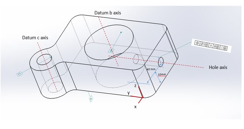
Does this mean that the hole can vary 1mm from datum a (easy to see) , and the same for datum b and c ?
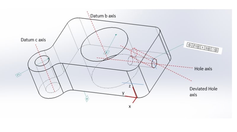
I am struggling to see how for b and c.. Are the datums just to fix the part on the CMM table so the hole can be measured ? Or does the control frame mean the hole can vary 1mm from a, b and c
Thank you.
Position Tolerance - Flat datum, and two circular datums.. How is this measured?
Does this mean that the hole can vary 1mm from datum a (easy to see) , and the same for datum b and c ?
I am struggling to see how for b and c.. Are the datums just to fix the part on the CMM table so the hole can be measured ? Or does the control frame mean the hole can vary 1mm from a, b and c
Thank you.
Position Tolerance - Flat datum, and two circular datums.. How is this measured?