Continue to Site

Eng-Tips is the largest engineering community on the Internet

Intelligent Work Forums for Engineering Professionals

  • Congratulations KootK on being selected by the Eng-Tips community for having the most helpful posts in the forums last week. Way to Go!

Position without Datums

Status
Not open for further replies.

dthom0425

Mechanical
Dec 6, 2018
46
Hi all,

See attached picture.

This is just a quick model that I through together for discussion. With this part, I made the pattern of those two bosses datum feature A - reason being is that these features would be the first features to interface to the receiving part. Datum feature B would be the flat face.

In looking at the positional tolerance feature control frame, I guess I'm being thrown off. With no datum feature references in the feature control frame, what does the positional tolerance actually mean? Is it just controlling the form?

Thanks
 
 https://files.engineering.com/getfile.aspx?folder=a09faf75-b4e9-4414-a5e4-dee725253e75&file=pinplate.JPG
Replies continue below

Recommended for you

Have you read any version of the standard? If so, which one?
 
dthom0425,

Just to point you in the right direction - its right there in the definition.

ASME Y14.5-2009 said:
7.2 POSITIONAL TOLERANCING
Position is the location of one or more features of size relative to one another or to one or more datums.

FYI - datum feature definition isn't just about what touches/interfaces FIRST, its what ultimately constrains the part in the associated DOF during function/assembly. If those pins/bosses interface first with a mating part HOWEVER they are clearance fit then it is clamped somehow to the flat face so that it constrains [z,u,v] (assuming z is perpendicular) then the flat face should probably be primary.
 
dthom0425,

It is not what feature goes FIRST or SECOND... Here is a good example from the standard below. I would consider swapping your primary and secondary datum features. In addition, I would also consider MMB for the two pins.

1_hsippa.png
 
dthom0425 said:
reason being is that these features would be the first features to interface to the receiving part.

As noted by Tarator, the datum precedence is not dictated by which feature is the first to contact the mating part, but by the amount of contact.

If you have access to ASME Y14.5-2009, check 4.18 DATUM FEATURE SELECTION PRACTICAL APPLICATION and Figure 4-36
 
Thanks for the responses. I operate off of Y14.5-2009.

What I was trying to get at was - normally position controls location/orientation. In the case I presented above, I suppose I'm controlling the location of the pins relative to each other? Is that correct? So they can only tilt/shift within the .005 cylindrical tolerance zone.

Function of the part: These pins engage into bushings (minimal clearance...about .001), which align the entire part in assembly and the flat surface (datum feature B) butts up against another flat surface. The part I modeled in the picture is just a representation of what I'm working with. The surface that butts up is actually fairly small (pad like features)that I don't believe would work out as a primary datum (hence my selection of the pins).

 
Apologies if I sound like a broken record. Perhaps putting your question side by side with the text in the standard will help.

In the case I presented above, I suppose I'm controlling the location of the pins relative to each other?
ASME Y14.5-2009 para 7.2 said:
Position is the location of one or more features of size relative to one another or to one or more datums.

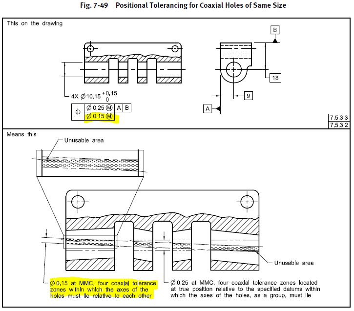
Perhaps two examples will help. The first is truly datumless, the holes are held in basic relationship to each other (0 basic/coaxial) for the second frame.

fig_7-49_owgrvm.jpg


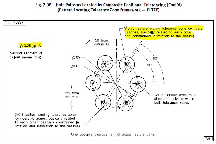
The second is where the singular datum feature A has no location relationship to the pattern of holes (flat face perpendicular to the holes). The tolerance zones are still held in basic location/orientation relative to each other, and only in orientation/rotation to datum feature A for the second frame. The only difference if A were removed is that the second frame would no longer be required to be constrained in rotation to A - the basic location relationship between the features in the pattern would not be changed.

fig_7-38_mx9erb.jpg


Hopefully I'm not creating additional confusion - but after re-reading your question and noticing the omission of orientation in your question (location/orientation vs. location only), I think there may be a gap in the understanding of how DOF are constrained which is maybe not explicitly set forth by the standard.

What I was trying to get at was - normally position controls location/orientation. In the case I presented above, I suppose I'm controlling the location of the pins relative to each other?

Constraint of location without first constraining some degree(s) of rotation is extremely suspect, if not prohibited by the geometry involved. Hence why orientation controls can constrain rotation only, but position constrains orientation and then location as applicable. For an example of what I mean, look at the first example (fig 7-49) and imagine what location constraint to A, B, or |A|B| would look like without orientation constraint to A, B, or |A|B|.
 
I look at that callout and say:

Because the references to [A] are RFS, the two pins will be hammered into tight fitting holes mating holes and those pins will be the sole orientation and location control; the use of the surface as is a needless complication as it does not offer any refinement to the [A|B] DRF. In fact, the flat surface will likely be warped by the interference/press fit required.
 
chez311,

Sorry - you may have slightly confused me.

So are you saying that the datumless position can essentially be treated like a FRTZ? That being, the pins are held in basic relationship (location to each other) and are free to tilt within the .005 true position assigned? I sketched a quick picture in mspaint - see attached.

If that's the case, I guess I'm still lost or maybe I'm overthinking this. With the datumless position, I'm trying to understand what (size, location, orientation or form) I am truly controlling. It seems like basic location to each other, but I guess I'm not understanding the orientation part of it. Orientation to what? There's no additional datum feature referenced so what is the .005 tol zone going back to? Which led me to believe that the datumless position, in this particular instance, would end up controlling form by the establishment of an inner/outer boundary at RFS.

I understand fig 7-49 - the coaxiality. I don't have coaxial features here so that's probably throwing me off too.

Thanks again
 
Orientation to each other. Sigh. They don't have to be parallel.
 
With the datumless position, I'm trying to understand what (size, location, orientation or form) I am truly controlling. It seems like basic location to each other, but I guess I'm not understanding the orientation part of it. Orientation to what?

Location and orientation to each other. You understand that the basic distance is fixed between the two tolerance zones, but in order to do so we must also constrain rotation relative to each other - ie: if the tolerance zones were allowed to tilt towards or away from each other, your basic distance would no longer be maintained. The feature axes (UAME axes) may shift/tilt within this tolerance zone but the tolerance zones themselves are fixed in basic location/orientation relative to each other. However since no datum features are specified (I call this datumless) then there is no location or orientation requirement to a particular DRF.

If you understand the coaxial case, its as simple as extrapolating what would happen if we were to have a nonzero basic distance between the feature axes. Coaxial features are just a special case where your basic distance is zero - the underlying concept is the same.
 
Status
Not open for further replies.

Part and Inventory Search

Sponsor