Continue to Site

Eng-Tips is the largest engineering community on the Internet

Intelligent Work Forums for Engineering Professionals

  • Congratulations KootK on being selected by the Eng-Tips community for having the most helpful posts in the forums last week. Way to Go!

Pressure drop in compressible flow 10

Status
Not open for further replies.

TomaszKruk

Civil/Environmental
Oct 2, 2019
33
Hello,

I have a problem to solve that seemed trivial at first, but kinda got out of hand quickly. I want to properly calculate pressure drop on a gas pipe on a chemical plant. I thought I'd find "plug and play" equations with iterations maybe, but after 2 days of reading I'm horribly confused.

Can someone point me into a direction of a legit source for compressible flow pressure drop equation? There will be no outlet to atmosphere, no flare - I need to calculate exact value of pressure drop on the line so the equipment downstream from my pipe won't work above design conditions. I did not select the working pressure or design the equipment downstream - all I got is obvious conclusions that I need a certain loss value or things might look bad.

I tried an older version (that is the one available for me) of the 410TP. Simple Darcy equation is easy enough to solve but untrustworhy. Darcy formula including Y factor is infuriating - you need to know the pressure drop in order to calculate Y, so the equation is useless to me.

I did solve a verion of the Isothermal flow equation provided, all good and well, but my spreadsheet is acting funny (probably excel finds it hard to iterate solution since I work with SI units and my pressure is around 40 bar - the equation works for Pa only). I'd like to verify the results. Especially that I suspect it works best for mass flow calculations, if the pressure loss is given.

I found a webpage with free calc, but it gave me an error I'm too dumb to understand (supersonic outflow?). I even went thru the process of learning to use "." instead of "," and the Imperial units for it :(
I read a lot of sources but most of them I suspect are viable only for natural gas even though they do not state that directly (like Panhandle equation - I always believed it works for natural gas only, but there it was in a paper about gas flow thru pipes).

Gonna go with this one next:
Please help guys - this is the thing I've been hoping to get my teeth into, but need a good source or good book / paper on piping / chemical engineer level. So far I found a lot of things that just aren't right.

Thanks,
Thomas
 
Replies continue below

Recommended for you

Well...Crane should be a good source.

Try sharing your operating conditions here so we can review.

Daniel
Rio de Janeiro - Brazil
 
It can be done, but compressible flow via manual calcs is a bear and a half. Due to the compressible nature of the fluid, the velocity and density of the fluid are changing as you experience pressure drop.

If your velocities are are supersonic (Mach > 1) then things get worse due to pressure discontinuities.

I'd recommend software. It's important you have familiarity with the equations/concepts, but if your company doesn't have an Excel sheet already it'll be quite an effort to develop one.
 
There may be a couple of things to watch in your gas pressure drop problem.
You start picking up errors when you try doing a calculation with a large pressure drop from a long pipe. The equations use the average conditions in the pipe and we need to keep the inlet and outlet pressures near the average to keep some accuracy. And if the pressure drop is too much, sonic conditions might occur.

One other thing we need to look is pressure safety. You mentioned that you need to keep pipe outlet pressure below your equipment's design pressure. You generally must not do that by using the pressure drop in the pipe to get and keep you below that. Why? Because if the gas flow rate drops for any reason, the pressure drop will also be smaller and if your inlet pressure remains the same, you could exceed equipment allowable pressure. Let's get into that later. First, the pressure drop.

What's your inlet pressure, 40 Barg?
What's the pipe size and material?
How long is your pipe?
You say you have a gas pipe, but it apparently is not natural gas. So, what kind of gas is it?
What is the maximum design pressure of your downstream equipment?
And finally the temperature?

We need to look at those things to see if using one of several equations might be better than others.

I have not used this one yet, but it looks simple enough that it won't make us crazy. If you like, we can test it together to see if it gives accurate results.

 
You need to give us some specifics here so that we can point you in the right direction.

Pressure, velocity, pipe size, which "gas" etc.

to be honest it doesn't sound like a good idea to rely on pressure drop to give you a pressure that your equipment won't work above. Therein lies the potential for disaster.

Also how "exact" do you need to be. The more "exact", the harder it becomes.

If your end pressure is more than 5-10#% below the inlet pressure then you're not going to find anything accurate as a simple equation due to changes in density and velocity.

Engineering toolbox is usually a good place to start.

Remember - More details = better answers
Also: If you get a response it's polite to respond to it.
 
More info/details please.

It seems if the "blocked vent" scenario on your downstream equipment is credible, and there's not enough info. to know that for sure, everything will equalise to the same (high?) pressure as the upstream equipment. Is a PSV needed?

Good Luck,
Latexman
 
Hello guys,

thanks for answers. Especially nice to see LittleInch here who I remember helping me last year (I think with water flow, which I managed to get a handle of in the end - thanks!).

Pure Oxygen
33 000 Nm3/h
Iso pipe 219,1 x 8 mm
41,5 bar (a) compressor working pressure
321 ANSI stainless
Pipe run of about 100 m
Mean calculated velocity (calculated with the thermodynamics in mind) - 12 m/s

The above would probably be enough to identify the job, but I'd still rather hide the temperature, since it will be revealing. Let's say it's 80 degrees celcius.

When it comes to static pressure, or flow regulation - both are accounted for. There is no case in plant's operation when the oxygen is allowed to be static in a pipe - either the process is ongoing or the pipe is depressurized and filled with nitrogen. The process is to run with max capacity - when the flow decreases so does the pressure. Even the overpressure is somehow taken into the account since they can adjust the compressor a bit. The problem is that the customer will abuse me till I give him the answer - they are demanding. And if it can't be done - I need to be certain that it can't.

+ I still want to learn :D

Edit1 - just saw another answer - yes, there is a PSV installed, but we could end up with it opened constantly (or rather - till they adjust the compressor). I'm tasked with determining if it will be so. Even if the answer is that I should recommend my company some software - I'd still very much want to get my teeth into compressible flow. Water hydraulics were a lot of fun.
 
I second Danschwind's suggestion of getting a copy of Crane TP 410 - easily worth the 75 USD (60 USD for the metric version) and it will present a method for dealing with compressible flows based on the Darcy equation and other simple flow situations (e.g. isothermal, adiabatic). There are special requirements for pure oxygen systems that are also worth reviewing for any sizing guidelines to manage the mean velocity, your company may have such guidelines or you can reference industry documents such as EIGA, CGA, etc.
 
I would guess by the time you corrected the 33,000 Nm3/h to actual flowing T and P (41.5 bar_a!) you could use the incompressible Darcy Weisbach equation and dP/P1 will be << 10%, maybe < 1%, and call it good. Check it out.

Good Luck,
Latexman
 
Well, as I said before I think Crane is a good place to start. Maybe you can specify your exacts doubts regarding its approach to compressible flow so we can try to aid you? I didn't really understood what "Y" factor in Darcy you are referring to, but I'm not with my Crane beside me to check...can't recall any Y in the formula though.

But anyway, quickly plugging your numbers here, I got a velocity of 8.8 m/s considering 80°C and 8" Sch 40 pipe and a pressure drop of 0,13 bar per 100m. If I change the inlet density to get 12 m/s as you have calculated, I instead get 0,17 bar per 100m.

By the way, an unspoken rule regarding compressible flow: always define what your standard conditions are :)


Daniel
Rio de Janeiro - Brazil
 
It will be critical what happens in the downstream equipment. Does it operate at lower pressure? If so, that could affect the calculus.

That’s one of the problems of getting incomplete information.

Good Luck,
Latexman
 
Hello,

thanks for the answers. I got a pressure drop of around 0,26 bar (a) using the mass flow equation.

When it comes to "Y" factor - I meant an equation I found this in Crane:
w = 1.111 x 10^(-6) x Y x d^(2) * (dp / K / V)^(1/2)

where V is specific volume of fluid. The Paper is dated so maybe the equation is not there anymore. All in all - it gives 3 equations for solving pressure drop in compressible flow. One of them is the above, the other is a version of Darcy equation for gases, and the third is the iteration equation with mass flow in it.

Thank you for calculating the pressure drop. Can you guys point me to some good source for engineers, aside Crane?
 
I recommend that you have a good look at the P&ID of the process to satisfy yourself how the pressure in the destination vessel is controlled. It will not be controlled by the pressure drop in the gas line feeding it from the compressor. The pressure will be controlled by a valve at the inlet or outlet of the vessel - or even a combination of a flow control valve on the inlet and a pressure control valve on the outlet. In general the pressure drop in the line would be kept low so that a flow control valve at the inlet to the destination vessel "sees" a relatively constant pressure when the flow rate changes.

Compressible flow is really not the mystery many people make it out to be. In the Darcy-Weisbach equation for incompressible flow there are 3 varying parameters that are usually regarded as constant for a given pipeline. These are the friction factor, the density and the velocity - although the last 2 are effectively the same thing. Let's consider these parameters.

The friction factor depends on the Reynolds number which for a circular pipe is calculated as Re = (4/pi) x Mass flowrate / (viscosity x diameter). Usually we are considering the case of constant mass flow and constant diameter so the friction factor will change with the viscosity only. The viscosity is a function mainly of temperature, with a weak dependence on pressure. This is true of compressible and incompressible flow and in all but the most extreme cases we can take an average viscosity and assume that the friction factor is constant over the length of the pipe. So in this respect compressible flow is no more complicated than incompressible flow.

In incompressible flow we assume the fluid density is constant - this is the definition of incompressible. However, with compressible fluids the density, and therefore the velocity, changes along the pipe as the pressure drops. The density will also change with temperature if the condition is not isothermal. Unless you are dealing with cryogenic gases where the temperature might increase along the length of the pipe, in real life the temperature will generally drop along the pipe. If the temperature drops the density is higher (and the velocity lower) than it would be if the temperature was constant. So the isothermal assumption is usually the conservative approach (i.e. higher calculated pressure drop) and in the overwhelming majority of process flows the isothermal assumption gives a good design. If we assume ideal gas behavior (or at least a constant compressibility factor) and isothermal conditions then we can calculate the density at any point along the pipe.

The changing density impacts the pressure drop in 2 ways. It takes energy to accelerate the gas, and the higher velocity increases the friction. Crane Eq 1-6 takes both of these factors into account but sometimes the acceleration is ignored and Eq 1-7 is adequate. Once the formula has been programmed it is no extra work to use the full equation so unless you are doing hand calculations the simplified formula has no place in an engineer's toolkit.

Now that I have written this rather lengthy explanation, let me tell you that it is all irrelevant to your case. Virtually all texts will tell you that if the pressure drop calculated using the incompressible (Darcy-Weisbach) equation is less than 10% of the upstream pressure (in absolute terms) the result is "good enough". This is very easy to test with software like AioFlo where a single click will toggle between the incompressible and compressible models. The pressure drops calculated by the 2 models only differ in the 4th significant digit and the calculated pressure drop is about 0.5% of the inlet pressure so you will be very safe using the Darcy-Weisbach formula in this case.

One of the better fluids texts (IMHO) is Rennels and Hudson, but it might go into more detail than you need.


Katmar Software - AioFlo Pipe Hydraulics

"An undefined problem has an infinite number of solutions"
 
Can't get a better explanation than what Harvey has provided.

Both him and Latexman highlighted something important: the number I gave you and the number you calculated means absolutely nothing without context.

You hinted that your process may be sensitive and not-shareable, so try to review it in greater detail.

Daniel
Rio de Janeiro - Brazil
 
thanks for all the answers guys.

I understand a bit more now.
 
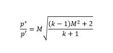
To be theoretically correct the following should be the procedure (air is used)(Ref Streeter)

1. You know friction factor, f, length, l, and dia, D, inlet Mach No M_0
2. Calculate Mach No M at distance l using(Use software like Matlab/Mathcad)
image_phqdce.png


4. For sonic flow at outlet (M=1,hypothetical) calculate the outlet pressure p^*. P_1 is inlet pressure.
image_c5vhr2.png

5. Calculate p' with inlet Mach no M as calculated.
image_stswtn.png

6. Pressure drop is
image_p5dw6p.png
 
With the given data and Streeter compressible flow formulae I got 0.2248 bar pressure drop. Quite close to results calculated earlier.
 
Thank you for your input. I should come back to pressure loss soonish (I hope)- all the post will be of great help then. Calculating same values with different equations will allow me to verify results and learn the ropes.

Cheers!
 
The Crane 410 book, buy used... and "the dynamics and thermodynamics of Compressible Fluid Flow, by: Ascher H. Shapiro.
Also, the friction factor for liquids is fm and for gases it is ff. ff = 1/4 fm. It took me a while to find this out.

The Crane book is a great start, but they drop you off in no-mans-land after a short version of compressible flow. Your final information will be in the second reference. Compressible gas High flow rates are weird stuff. First, calculate the reference M-Mach number. This is to find out if you have a choke situation. Then proceed with what the two references guide you.


DBrabley
 
DBradley said:
Also, the friction factor for liquids is fm and for gases it is ff. ff = 1/4 fm.

Ummm, f[sub]Darcy[/sub] = 4 x f[sub]Fanning[/sub].

I'm not sure about this f[sub]liquid[/sub] / f[sub]gas[/sub] stuff.

Good Luck,
Latexman
 
Status
Not open for further replies.

Part and Inventory Search

Sponsor