Why didn't you do your assignment first?
Fine, I'll tell you one method, but you will have to figure out a different way for your assignment, otherwise it's cheating.
First step is to define the basic relationship between the 3 planar surfaces forming the datum feature. I can place a coordinate system in a random location outside the part, and define each theoretical plane by 3 points that have tabulated coordinates in said coordinate system.
Second step is to limit the form and mutual orientation deviations of the actual surfaces based on the common true profile that was just defined for this group of features. A surface profile feature control frame that applies 3X and has leaders to the surfaces would specify a tolerance with no datum references.
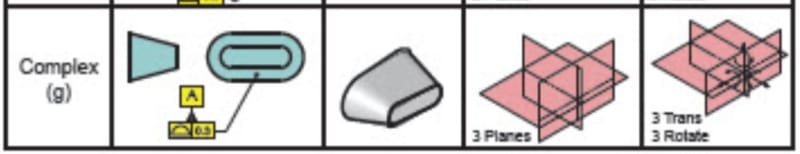
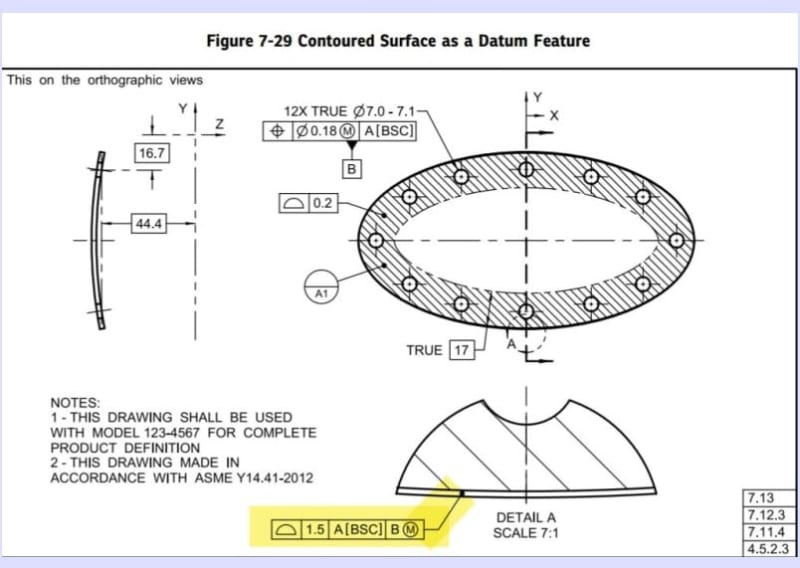
Third step is to label the group of features as a datum feature. The way this is done will affect the datum establishment later. A practical way could be selecting one point on each surface (possibly from the same points already mentioned) and designate them as datum targets such as A1, A2, and A3 - if that is functionally appropriate. The datum simulation device would have to contact the part at these 3 locations. Alternatively, and to stay as close as possible to figure 7-3 (g) which was the original topic, one could attach the datum feature symbol to the profile feature control frame which controls the 3 surfaces. In this case, the datum feature simulator would have the exact shape of the basically defined group of 3 planar surfaces.
Fourth step - deriving the DRF. The three orthogonal datum planes can be established by the same coordinate system that was used to basically define the datum feature.
(Fifth step - controlling the rest of the features on the part - the DRF that was established above will be the origin for the tolerance zones for the other two faces. They will be controlled for profile relative to the datum feature described above.)
Now do your assignment and use a different method.