Continue to Site

Eng-Tips is the largest engineering community on the Internet

Intelligent Work Forums for Engineering Professionals

  • Congratulations KootK on being selected by the Eng-Tips community for having the most helpful posts in the forums last week. Way to Go!

Rafter without fly brace? 22

Status
Not open for further replies.

fourpm

Industrial
Oct 12, 2019
13
I am designing rafters to AS4100 and wondering what if I don't use fly brace. I understand that with fly brace it will give you full restraint. But if I don't use fly brace, will the purlin above be considered as lateral restraint for rafter under uplift? If so. can I take the purlin spacing as segment and the only factor that changes without fly brace is kt?
I have the same question when it comes the continuous steel floor beam design where Z/C floor joints sit on top of the beam. What segment should I take for the beam near the support? Can I take the floor joists spacing as segment with lateral restraint? Can anyone give me some examples? I have read some manuals but the examples they have are simply supported beams only. Thank you.
 
Replies continue below

Recommended for you

Human909 said:
"there is some recent doubt as to whether lateral restraints on equal flanged I or W shapes can restrain the overall cross section laterally"

1) That's interesting and, I think, highlights the need to always be thinking of buckling in terms of a hierarchical, many mode process.

2) Of course a single flange L-brace does in fact restraint weak axis buckling. The question is, with that restrained, what mode is next in the sequence?

3) The next mode for a purely axial member would likely be pure torsional buckling, in this case constrained about the axis of the braced flange.

4) In my experience, even unconstrained torsional column buckling almost never governs for two fanged sections. It's an easy enough check though.

5) We could model this easily enough but it's probably a topic best left for another thread in order to be sensitive to everybody's fatigue levels.
 
Kootk said:
- No warping restraint to flanges at beam ends.
- 250kip downward point load at midspan applied to top flange.
- Weightless beam.

I think this should be:
- 250kip 12KIP downward point load at midspan applied to top flange.

EIT
 
Kootk said:
2) Of course a single flange L-brace does in fact restraint weak axis buckling. The question is, with that restrained, what mode is next in the sequence?
In pure compression you are pretty close to Euler theory land and you really are only thinking about 1 mode of buckling in each axis. Add your restraints, get your effective lengths anway you go. The next mode I suspect would be restrained flange minor axis buckling which would involve twisting of the section.

I imagine some engineers were counting L restrains on flanges to act as minor axis compression restraints. Think purlins on a portal frame building. That isn't something I'd like do. I'd use a centrodal lateral brace or fly bracing.

I'm currently in the process of designing a clad structure and I'm generally ignoring the restraint effects of the purlins except for a fews the points of fly braces. Moment reversal means adding a bunch of Ls on one side doesn't particularly help things much anyway. I've also chosen to avoid fly braces in the roof by using and H-beam because they'd be a pain to install. The lower columns, well there is 1400tonnes sitting on the 10mx35m structure. I'm not leaving compression buckling restrains to the purlins!

I'll see what I can get done now on NASTRAN. I might even through in the pure compression scenario in for fun.
 
RFreund said:
I think this should be:

Corrected, thank you.

human909 said:
I'd use a centrodal lateral brace or fly bracing.

And there's the rub. I believe that a centroidal lateral brace would be no better than a single flange lateral brace and may well be a bit worse. Both bracing schemes would eliminate full length weak axis buckling. To the extent torsional buckling would be the next mode in line, the flange brace would be better than the centroidal brace because the centroidal brace would do nothing at all to restrain the cross section twist which is the crux of torsional column buckling. It sounds as though we're heading for another model-off after all...
 
KootK said:
I believe that a centroidal lateral brace would be no better than a single flange lateral brace and may well be a bit worse. Both bracing schemes would eliminate full length weak axis buckling. To the extent torsional buckling would be the next mode in line, the flange brace would be better than the centroidal brace because the centroidal brace would do nothing at all to restrain the cross section twist which is the crux of torsional column buckling. It sounds as though we're heading for another model-off after all...

I couldn't resist looking into this so I took our W12 example and modeled it as a column with 100 k axial. It seems that I was partially wrong in my statement above.

The clips below show:

- The first three buckling modes with a mid-span, weak axis restraint at the column centroid.

- The first three buckling modes with a mid-span, weak axis restraint at one of the column flanges.

Here's what I see for takeaways:

1) For an eigenvalue buckling analysis, the first mode capacity for both brace arrangements is identical. I had this part right.

2) A centroidal brace is better for subsequent, higher energy buckling. The first torsional mode for the centroidal bracing happens at twice the load of the flange bracing. I had this part wrong.

c01_gxqdy8.jpg


c02_rpgmtk.jpg


c03_f7bsp1.jpg


c04_zyqxnq.jpg


c05_heq7jb.jpg


c06_zspgkj.jpg
 
First up:

Kootk said:
And there's the rub. I believe that a centroidal lateral brace would be no better than a single flange lateral brace and may well be a bit worse. Both bracing schemes would eliminate full length weak axis buckling. To the extent torsional buckling would be the next mode in line, the flange brace would be better than the centroidal brace because the centroidal brace would do nothing at all to restrain the cross section twist which is the crux of torsional column buckling. It sounds as though we're heading for another model-off after all...
I did a quick look.

SCENARIO: 31UB 10m, fully fixed ends, pure compression
No restraints: 196kN
Centeral restraint: 496kN
Central restraint at flange: 394kN (21% less)
Central restraint at purlin 130mm off flange: 287kN (42% less)


A 20% drop might be borderline significant, a 42% drop certainly is significant. I suspect this is where the caution is warranted when people are using purlins or similar as flange restrains when in reality they are restraining a cleat that can be a non negligible distance from the flange. (But again this is point lateral restraints of infinite stiffness laterally and zero rotational stiffness. In reality the restraint would have some rotational stiffness and non infinite lateral stiffness....) That said I'd hope the purlin spacing is close enough that it completely wipes out minor axis buckling... Either way I think that is another topic.

I'll follow up with the W10x12
 
This one's for the AISC crowd.

When knocking on the door of this thread, my hope was always that I'd walk away from it with a little candy in hand. And not just a sucker either but, rather, a full sized bag of chips or a three pack of peanut-butter cups. You know, some pearls of wisdom for use in my own, real work using the AISC standard. I believe that I have that now and I'd like to share it, both as an act of friendly dissemination and to provide others an opportunity to critique what I think I now know.

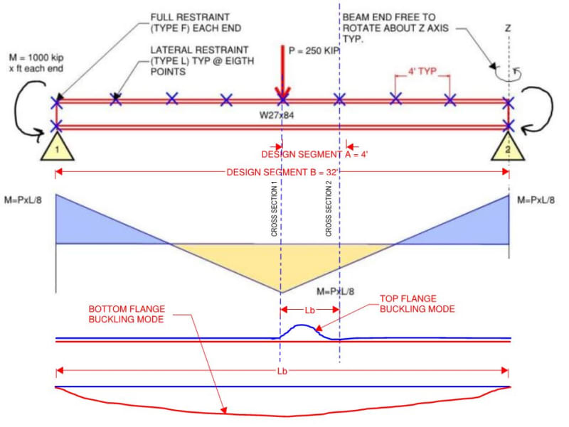
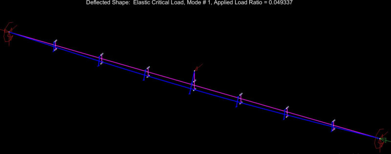
We AISC'ers don't seem to have an under-capacity LTB problem and, as such, do not need to change our ways just yet. That said, the LTB story that now plays in my head is a much richer and more nuanced thing than the one that played in my head prior to this thread. I feel that there's value in that. Without further adieu, here are my before and after LTB stories, with reference to the beam shown below.

KOOTK LTB STORY BEFORE LTB THRILLA IN MANILA 2019

1) Check design segment {A} as top flange buckling @ [Lb = 4']

2) Check design segment {B} as bottom flange buckling @ [Lb = 32']

3) Pat self on back for a job well done.

KOOTK LTB STORY AFTER LTB THRILLA IN MANILA 2019

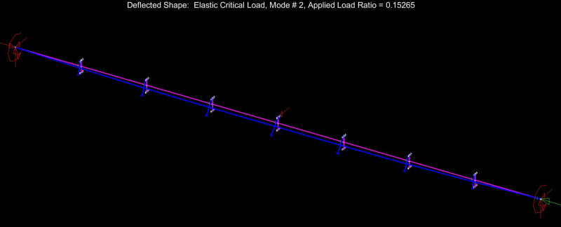
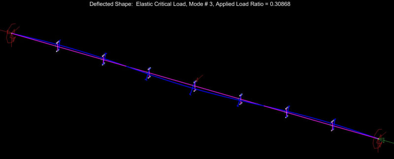
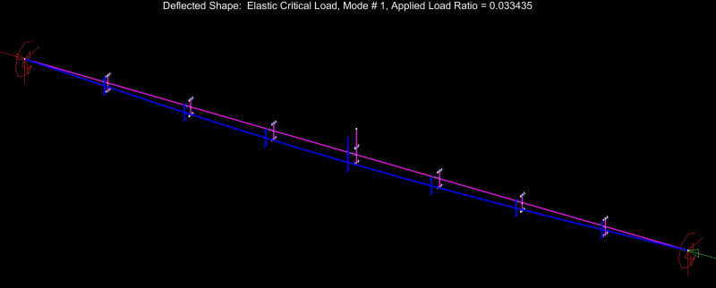
1) Check design segment {A} as top flange buckling @ [Lb = 4']

2) Recognize that #1 implicitly assumed that cross sections 1 & 2, bounding design segment [A], did not rotate appreciably. Marvel at this given that neither cross section is endowed with any physical, rotational restraint in the form of external bracing.

3) Recognize that the two things providing rotational restraint to cross sections 1 & 2 are the St. Venant torsional stiffness of the beam and the warping torsional stiffness of the beam. Further recognize that the warping torsional stiffness will dominate for most wide flange beams.

4) Recognize that the warping torsional stiffness of a wide flange beam basically amounts to the flanges acting as girts spanning horizontally between the rotationally restrained ends of the design segment. For this beam in particular, it's all about the bottom flange performing the girt function. So this is how cross sections 1 & 2 are rotationally stabilized. It's the bottom flange as stabilizing girt.

5) Given that the bottom flange is doing this important girt thing, question whether or not some kind of check should be performed on the bottom flange to ensure that it is strong and stiff enough to do the job. For a simple span beam with no bottom flange compression, no such check is performed. It seems that we are comfortable assuming that an all-tension flange can do the girt job effectively. And that's probably alright given that it really doesn't take much to brace a thing.

6) Recognize that the bottom flange is in compression over much of its length and will have a tendency to buckle between the ends of the beam. Further recognize that, if the bottom flange is allowed to buckle, it will kick the bottom flange out at cross sections 1 & 2 and, thus, utterly violate the assumption of near zero cross sectional rotation at those locations. What to do?

7) Check design segment as bottom flange buckling @ [Lb = 32']. In addition to checking for bottom flange buckling in its own right, this check rectifies #6 by allowing us to continue to assume that cross sections 1 & 2 remain rotation free because the bottom flange was not allowed to kick out.

8) Given that negative bending LTB will govern, consider taking advantage of constrained axis LTB which accounts for the benefit of the top flange restraints in the calculation for bottom flange LTB buckling. The trade off is additional calculation complexity. Reject this given that experience has shown that the capacity increase is only on the order of 20% because the center of LTB rotation tends to be pretty close to the top flange even in the absence of the top flange bracing. Deflection concerns probably govern the design anyhow.

9) Pat self on back for a job well done.

c01_vnyzf6.jpg
 
Can you run the next one with pinned ends and Fy = 500 ksi.
 
Human909 said:
I suspect this is where the caution is warranted when people are using purlins or similar as flange restrains when in reality they are restraining a cleat that can be a non negligible distance from the flange.

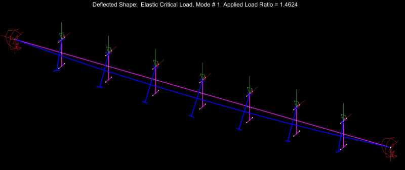
I see what you mean. First below is unbraced column. Second is a brace placed 12" off of the flange to hyperbolically simulate the cleat business. You're almost down to the unbraced braced value and it doesn't take much imagine to see why with the buckled shape staring back at you.

c02_zn8p4t.jpg


c01_vxmyra.jpg
 
KootK:

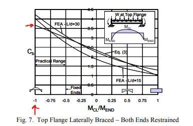
I've read thru the Yura document a few times and if I've understood it correctly Yura recommends a modified Cb formula to capture beams with reverse curvature.

Plotted in Fig. 7 in the document:
Capture_wpz4gn.jpg


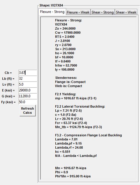
for the 32' - W27x84 beam this would yield a Cb of 3.67
So redoing the check with Lb = 32' and the new Yura Cb, I'm getting that yielding is the controlling limit state not Lateral Torsional Buckling, however if I am understanding your Mastan runs correctly they seem to indicate a much lower LTB value?

Capture_r9kbkp.jpg


Open Source Structural Applications:
 
Kootk said:
1) For an eigenvalue buckling analysis, the first mode capacity for both brace arrangements is identical. I had this part right.
And this is where the Mastan models seem to fall over. That is not at all logically consistant for the buckling model to be identical. You would expect some change in the mode even if it is small.
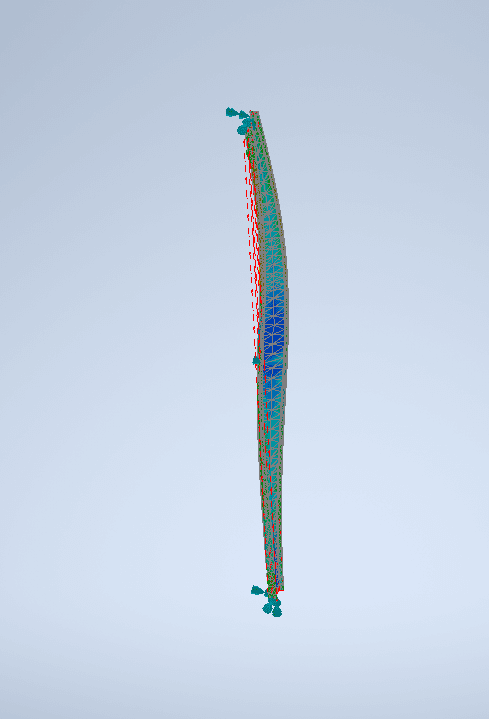
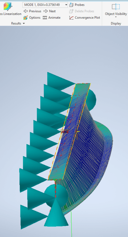
Here is my buckled shape:
temp_ycuigg.png


And here is my first mode for the W10x12. The load factor is 0.375
temp_tfpmhp.png


(This seems differnt from yours but maybe I've made a mistake. You can see my constraints in my picture. Load is 53.38kN.
 
Human said:
(This seems differnt from yours but maybe I've made a mistake. You can see my constraints in my picture. Load is 53.38kN.

Nope, the mode shape looks identical to mine.

Human909 said:
And here is my first mode for the W10x12. The load factor is 0.375

Well below plastic yield moment, as my models indicated.

That's good enough for my purposes. Thanks for the run.

 
Human909 said:
And this is where the Mastan models seem to fall over.

Perhaps, but it strikes me as premature to be blaming Mastan already. To quote a friend from, like, hours ago:

Also I wouldn't put the blame on NASTRAN MASTAN, I'd put the blame on the user (myself)...

Additionally, I still don't know much about your model. Can you run the W12x10 with pinned ends and Fy = 500 psi and post something showing:

1) The first three buckled mode shapes and;

2) What your FEM mesh looks like.

Lastly, I disagree with this.

Human909 said:
That is not at all logically consistant for the buckling model to be identical. You would expect some change in the mode even if it is small.
Here is my buckled shape:

Like anything else in buckling restraint, I would suspect that there is some value of offset at which the first mode buckling shape switches from one involving twist to one involving only S-shape weak axis buckling. And I'd absolutely expect that value of offset to be greater than zero. In fact, if your model can't be made to show that, I'd question its validity. Can you put the restraint at, say, 2" from the column centroid?
 
Celt83 said:
So redoing the check with Lb = 32' and the new Yura Cb, I'm getting that yielding is the controlling limit state not Lateral Torsional Buckling, however if I am understanding your Mastan runs correctly they seem to indicate a much lower LTB value?

It's a fair bit more nuanced than that I think. You'll notice that Yura's chart was based on a uniform load distribution whereas my W27x84 example modeled a concentrated load. The distribution of the load impacts the stability of the beam with greater load concentration towards midspan producing lower capacities.

To provide a more meaningful comparison, I reran the beam as fixed ended with a uniform load.

M_LTB_Mastan_Concentrated = 690 k-ft

M_LTB_Mastan_Uniform = 854.2 k-ft

Cb_Yura = 3.00

M_LTB_Celt83 = 919.4 k-ft (Your calc adjusted by ratio 3.00/3.67)

854.2 k-ft / 919.4 k-ft = 93%. As approximate as this stuff is, that's a non-discrepancy in my book.

c01_r3zjsw.jpg
 
KootK said:
Like anything else in buckling restraint, I would suspect that there is some value of offset at which the first mode buckling shape switches from one involving twist to one involving only S-shape weak axis buckling. And I'd absolutely expect that value of offset to be greater than zero.

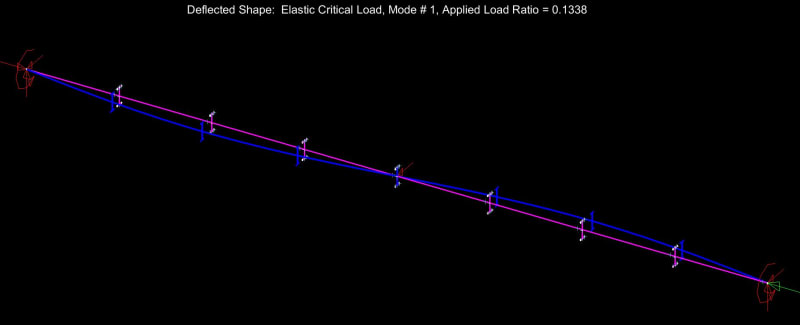
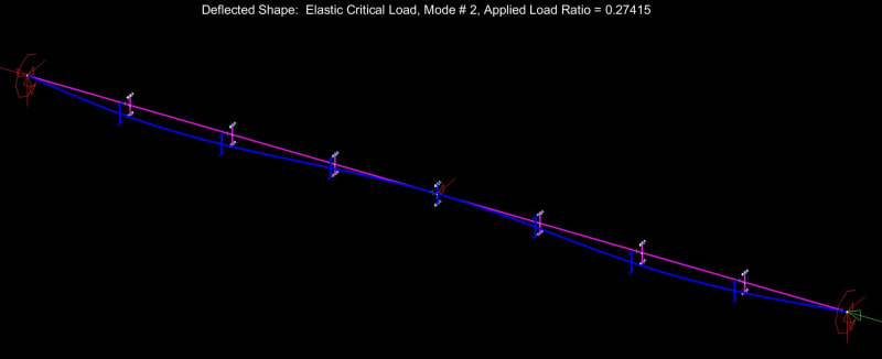
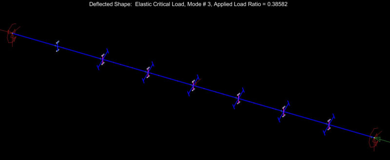
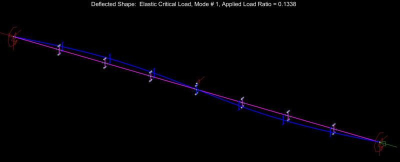
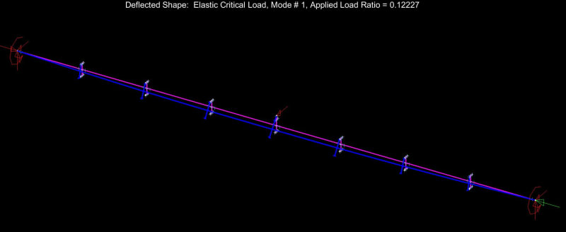
In support of that, I found the bifurcation offset point for the W10x12 column by trial and error.

1) With the restraint 2" from the flange or less, it's pure S-shape weak axis buckling. First clip below.

2) With the restraint 3" from the flange or more, it's a full length lateral torsional thing. Second clip below.

3) So my transition point is somewhere between 7" and 8" from the column centroid and outside of the flange altogether.

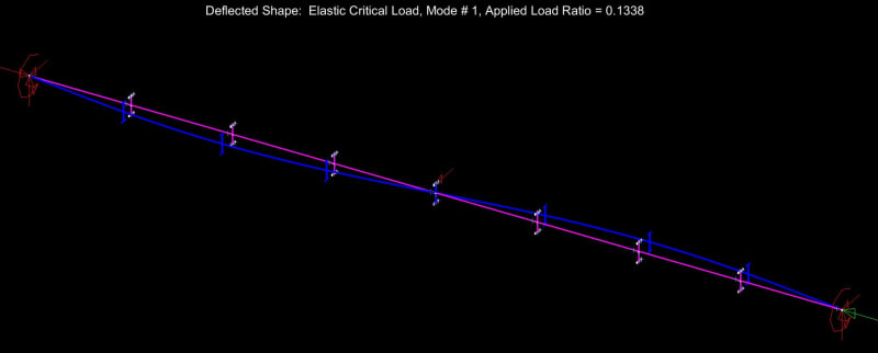
4) I would expect any offset value less than 7" from the centroid to have the same ALR at 0.1338.

5) I would expect this to vary with varying column size. Sometimes the transition point is inside the flanges and sometimes it's not.

c01_dsszp6.jpg


c02_wwmyjx.jpg
 
Human909 said:
And here is my first mode for the W10x12. The load factor is 0.375

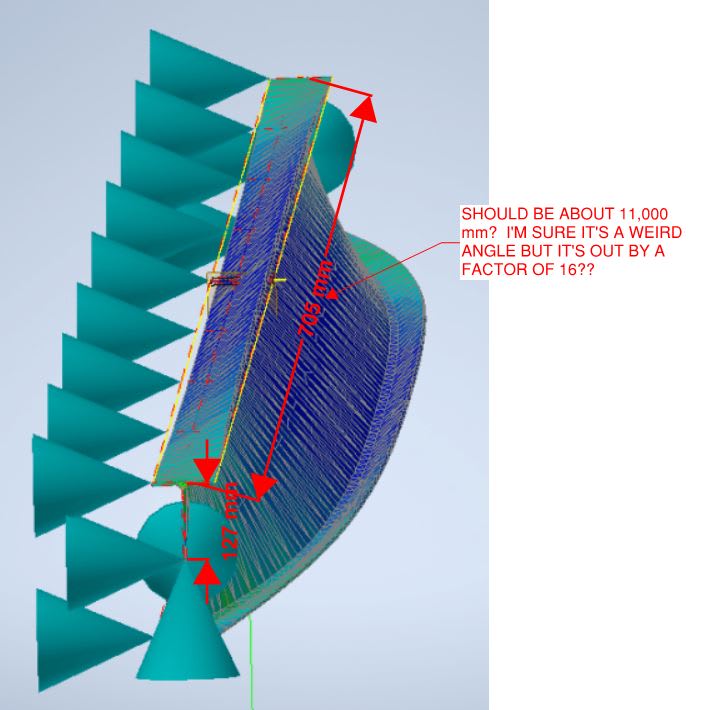
Something seems off with the proportions here. Are you sure that your beam isn't 36 inches instead of 36 feet? I get that there'll be some perspective at work but this scales off by a factor of 16.

c01_axij0x.jpg
 
Length is correct. There is significant perspertive foreshortening. I generally rotate the models in a manner I believe best conveys the buckling shape.

Kootk said:
Like anything else in buckling restraint, I would suspect that there is some value of offset at which the first mode buckling shape switches from one involving twist to one involving only S-shape weak axis buckling. And I'd absolutely expect that value of offset to be greater than zero. In fact, if your model can't be made to show that, I'd question its validity.

Except the change in the first mode of buckling isn't binary. Nor can you think of a buckling mode as pure torsional or pure minor axis once you start offsetting the minor axis restrain. It becomes a mix of both hence the reduction in the buckling threshold. Any program that is outputing identical results despite a shift in the minor axis restraint is doing not doing the job completely. I'm not sure what Mastran does but if it runs sepparate buckling analysis on orthogonal planes then this might explain the outcomes. As far as the buckling shape goes it pretty much starts off as an S shape and then a twisted S shape as restraint moves further out. Since this starts off as the first buckling mode and continues to reduce in its threshold value then there is never any sharp transition to a different mode.

FEA buckling analysis is agnostic when it comes to the various buckling behaviours.

KootK said:
Can you put the restraint at, say, 2" from the column centroid?
I can put it 1mm from the centroid and you will still get a reduced result. The buckling threashold is a decreasing monotonic function with regard to the restraint distance from the centroid.


A simple test with a plastic ruler could readily show this minor axis buckling with rotation.
 
Human909 said:
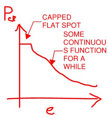
Except the change in the first mode of buckling isn't binary.

Not binary, just discontinuous with a flat spot. Something like this.

c01_gjkcsb.jpg


Human909 said:
Nor can you think of a buckling mode as pure torsional or pure minor axis once you start offsetting the minor axis restrain.

You most certainly can if you're not modelling imperfections and using an eigenvalue analysis.

Human909 said:
The buckling threashold is a decreasing monotonic function with regard to the restraint distance from the centroid.

Can you offer some proof of that, as I did for my stance in my previous post?

Human909 said:
I'm not sure what Mastran does but if it runs sepparate buckling analysis on orthogonal planes then this might explain the outcomes.

Nope, it's just straight up eigenvalue in 3D.

Human909 said:
A simple test with a plastic ruler could readily show this minor axis buckling with rotation.

Only because the ruler would represent a real world problem replete with imperfections. Take out the imperfections and it's a different ball game.
 
I think you are misunderstanding the differences between these modelling approaches.

A lateral brace that is eccentric (aka non central) IS an imperfection in this context.

Yes I do have proof I can do 10mm, 75mm and 149mm. But currently not in front of the computer. (I was going to do 1mm but I'd need to massively refine the mesh for that behaviour.)
 
Human909 said:
I think you are misunderstanding the differences between these modelling approaches.

I know almost nothing about your modeling approach. Tell me about it if your think there's something that I need to know but don't.

Human909 said:
A lateral brace that is eccentric (aka non central) IS an imperfection in this context.

Are you telling me that the offset brace would affect behavior prior to the attainment of the weak axis Euler load in the absence of other imperfections?

Human909 said:
Yes I do have proof I can do 1mm, 10mm, 75mm and 149mm. But currently not in front of the computer.

It's not actually proof until after you run the models. I might be able to get my hands on an educational version of NASTRAN. Can you send me dropbox links to your W10x12 beam and column models so that I can tinker with them?
 
Status
Not open for further replies.

Part and Inventory Search

Sponsor