Continue to Site

Eng-Tips is the largest engineering community on the Internet

Intelligent Work Forums for Engineering Professionals

  • Congratulations KootK on being selected by the Eng-Tips community for having the most helpful posts in the forums last week. Way to Go!

Rafter without fly brace? 22

Status
Not open for further replies.

fourpm

Industrial
Oct 12, 2019
13
I am designing rafters to AS4100 and wondering what if I don't use fly brace. I understand that with fly brace it will give you full restraint. But if I don't use fly brace, will the purlin above be considered as lateral restraint for rafter under uplift? If so. can I take the purlin spacing as segment and the only factor that changes without fly brace is kt?
I have the same question when it comes the continuous steel floor beam design where Z/C floor joints sit on top of the beam. What segment should I take for the beam near the support? Can I take the floor joists spacing as segment with lateral restraint? Can anyone give me some examples? I have read some manuals but the examples they have are simply supported beams only. Thank you.
 
Replies continue below

Recommended for you

Kookt said:
Are you telling me that the offset brace would affect behavior prior to the attainment of the weak axis Euler load in the absence of other imperfections?
That is EXACTLY what I am telling you. And that is exactly what you would expect in REAL world buckling even without imperfections. The change in the restraint position decreases the required energy to buckle the beam.

Kookt said:
It's not actually proof until after you run the models.
Well yeah well had run models just not the full set. And my phone which my last post was from doesn't have NASTRAN. BTW I removed my claim of running a 1mm model as the mesh size would get stupid to do that, so would the decimal places of difference. Anway here are my results.

MODEL: 31UB 10m, fully fixed ends, pure compression (200mm nominal mesh size setting, with refinements around necessary features)
RESULTS:
-Minor axis lateral brace on web at 5m, offset from beam central axis. Brace is at a point.
0mm OFFSET: 494.146kN
10mm OFFSET: 493.801kN
50mm OFFSET: 484.698kN
100mm OFFSET: 452.135kN
149mm OFFSET: 400.194kN (ON FLANGE RATHER THAN WEB)
(Note the last value 1.5% different from the one give a couple of hours ago. Once you change the mesh you are always going to expect differences.)

All these buckling shapes are the lowest energy mode and are largely of an S shape. 0mm offset gives a perfect S shape with no twist the S rotates around the restraint at 0mm. The rest have a degree of twist as the S now rotates around an offset restraint.

Of course all the caveats apply regarding 'models' but the point is that you keep the same model and move the restraint out you are going to get decreasing buckling loads in a monotonic fashion. There is no way around this given this is the lowest buckling mode AND you are reducing the effectiveness of the restraint for each fraction of a mm you move it away from the centroid. If you buckling analysis doesn't give results that behave in this manner then it isn't going deep enough to andequately address the nuances brought up in this tangent topic and possibly the topic as a whole.

NASTRAN is FEA buckling analysis thus it deals with a real 3D body, aka the precise shape affects the behaviour. Whereas (correct me if I'm wrong) Mastran relies on section properties, which alone can never fully describe a member.

Kootk said:
I might be able to get my hands on an educational version of NASTRAN. Can you send me dropbox links to your W10x12 beam and column models so that I can tinker with them?
You should be able to get 30days free.

Kootk said:
I know almost nothing about your modeling approach. Tell me about it if your think there's something that I need to know but don't.
FEA has been the brave new world of computerised modeling for decades now in many fields. Others can explain it far better than I can.

Of course like many 'models' it is not the real world. It is dependent on sensible inputs and sensible interpretation of outputs. However GOOD FEA has a better chance of approaching the real world than a few equations and a few characteristic properties of a section. This is especially so when things get non symetric.
 
Thanks for the info Human909. With regard to the column investigation, it sounds as though the discrepancy simply arises because I'm doing a bifurcation analysis and you're doing something fancier that embodies some manner of system perterbation, even if that's just mesh asymmetry. With the full blown FEM software there's usually an "analysis options" menu screen with gobs of options to choose from. Can you post a screen capture of that input screen with the options selected as you have done for your models so far? I'm fairly well versed in FEM and this would go a long way towards my understanding the nature of the models that you're running.

Are you able to share some of your recent models with me?

KootK said:
Can you send me dropbox links to your W10x12 beam and column models so that I can tinker with them?

I'll have a steep learning curve to deal with if I start tinkering with NASTRAN. Having your files as starters would be a great help. It would also help me to understand your modelling choices.

Human909 said:
Whereas (correct me if I'm wrong) Mastran relies on section properties, which alone can never fully describe a member.

I believe that is correct although, for the benefit of anyone interested in Mastan, I should mention that it can do a good deal more than we've been doing with it in this thread. We've just been doing linear elastic eigenvalue buckling models so far but the software also has the ability to study plasticity and run non-linear second order analyses. With regard to the column discussion, one could do a true second order analysis in Mastan, along with some manner of imperfection representation, and arrive at similar results to what you've been producing.

Human909 said:
If you buckling analysis doesn't give results that behave in this manner then it isn't going deep enough to andequately address the nuances brought up in this tangent topic and possibly the topic as a whole.

In my opinion, Mastan is actually a better tool than full blown FEM for what we've been trying to do in this thread. Full blown FEM surely is a more accurate representation of reality but, I would argue, reality isn't really what were trying to parse out here. Instead, it seems to me that we're mostly trying to reconcile code provisions with the underlying LTB theory that informed them. And that underlying theory was linear elastic bifurcation buckling, just what we've been doing with Mastan but with a slightly higher degree of sophistication. In this respect, I feel that full blown FEM kind of "overshoots" things in making direct comparisons to code provisions less meaningful. That said, it is of great value here to be able to use Nastran to corroborate the modes shapes and capacities predicted by Mastan. Were Nastran mode shapes wildy different that the Mastan modes shapes then I would definitely be concerned.
 
In this post, I'm going to pose, and attempt to answer, this hypothetical question: if there is an error in AS4100's LTB provisions, and I do not know with any certainty that there is, what would be the least invasive way to rectify it? I feel that the exercise has value for two reasons:

a) If there is an error in AS4100, this might help to point us to its root source.

b) If there is an error in AS4100, this might help to point us to how it might be corrected.

In my final anaylysis, I've come up with the only potential error in AS4100 being one of omission, as follows.

@tomfh: now it's time to offer your critique of this if you wish. Fire away.

KootK's Proposed Addition to AS4100 said:
Beam segments containing moment reversals shall be investigated for LTB stability as follows:

1) Perform an LTB investigation considering the top flange to be the critical flange for its entire length and;

2) Perform an LTB investigation considering the bottom flange to be the critical flange for its entire length.

Were this change to be made, I see the following items being resolved:

A) no more issue with AS4100 potentially overestimating LTB capacity at moment reversals.

B) no more issue with AS4100 seeming to assume buckled shapes vastly different from Mastan/Nastran.

C) no more issue with conflicting definitions of the critical flange.

D) AS4100 and AISC become philosophically identical which is appealing if extraneous.

E) No more issue with AS4100 seeming to assume rotational stability where buckling analysis predicts otherwise.

 
Kootk said:
Thanks for the info Human909. With regard to the column investigation, it sounds as though the discrepancy simply arises because I'm doing a bifurcation analysis and you're doing something fancier that embodies some manner of system perterbation, even if that's just mesh asymmetry.
No it isn't just system pertebation, though you are correct mesh asymetry can introduce some imperfections but generally that is a long way from real imperfection. The restraint itself introduces asymetry in the buckling mode. As I have highlighted an offset restrain reduces the required energy for minor axis buckling in a decreasing monotonic fashion with regard to the offset. That is expected from theory, from models and you expect that to be true in real life though imperfection might it an imperfect "decreasing monotonic" relationship.

Kootk said:
With the full blown FEM software there's usually an "analysis options" menu screen with gobs of options to choose from. Can you post a screen capture of that input screen with the options selected as you have done for your models so far? I'm fairly well versed in FEM and this would go a long way towards my understanding the nature of the models that you're running.
I think we should start buckling analysis thread to address this and other aspects being discussed in this tangent. Keep this thread to the AS4100 rather than indepth buckling modelling

Kootk said:
Are you able to share some of your recent models with me?
Get it up and running and I should be able to.

Kootk said:
With regard to the column discussion, one could do a true second order analysis in Mastan, along with some manner of imperfection representation, and arrive at similar results to what you've been producing.
You remain under the false impression that these results are caused by "imperfections". They are not. The effect of an off set lateral brace in minor axis buckling is a reduction in the critical buckling threshold with or without real world imperfections. Oh and I think you have just created the next challenge for yourself.

Kootk said:
Mastan is actually a better tool than full blown FEM for what we've been trying to do in this thread.
Fair call I can see some merit to this depending on your approach. My understanding is Mastan is going to more likely mimic classic section buckling as is considered by the code(s). FEA buckling analysis can be used to more accurate model the affects of real work restraint stiffnesses if you go that far (which I haven't in this thread.)


Like I said feel free to start a new thread to discuss buckling modelling. In the meantime here are a few videos to cover the basics. (I've only watched the first short one.)

 
Human,

In your opinion do your NASTRAN beam models show lower capacity than AS4100’s basic method?

Is your basic elastic buckling load coming out lower than the AS4100 capacity using the normal method?
 
Human909 said:
Like I said feel free to start a new thread to discuss buckling modelling.

Nah, I like this part of the discussion right where it is as I feel that difference between our modelling efforts are an important part of the current discussion.

KootK said:
Can you post a screen capture of that input screen with the options selected as you have done for your models so far? I'm fairly well versed in FEM and this would go a long way towards my understanding the nature of the models that you're running.

@Human: can you please provide that? You're using very sophisticated software with, I'm sure, oodles of option settings. It's difficult to know how to interpret your results without knowing much about the modelling choices that you've made.

Human909 said:
Are you able to share some of your recent models with me?

Human909 said:
Get it up and running and I should be able to.

Can you please send me a link to your models soon, before I get it up and running? As you can imagine, getting set up with a whole new software package is going to require a significant time investment on my part. I'd like to have some trial models in hand to work with before I invest that effort. What's the difference on your end between sharing the models now or sharing them later?

 
The settings are largely the default. Messing around with the setting doesn't and shouldn't changes things beyond going for further refinement. It is the constraints, loading and 3D model that are the main influence. You really don't need 100 screenshots of things.

This is the column model.
 
human909 said:
You really don't need 100 screenshots of things.

I didn't ask for 100 screenshots. I asked for one. How. Hard. Is that?

human909 said:
It is the constraints, loading and 3D model that are the main influence.

If you think that those are the only variables that significantly affect the output of your 3D, shell element, non-linear, finite element buckling analysis software, you might want to watch a few YouTube videos yourself. I dunno:

- Nonlinear buckling analysis vs linear buckling analysis
- Element mesh size and shape
- Element type / formulation.
- Load step increment.
- Convergence tolerance.

human909 said:
The settings are largely the default.

Scary.

Thanks for the model.
 
human909 said:
The restraint itself introduces asymetry in the buckling mode. As I have highlighted an offset restrain reduces the required energy for minor axis buckling in a decreasing monotonic fashion with regard to the offset. That is expected from theory, from models...

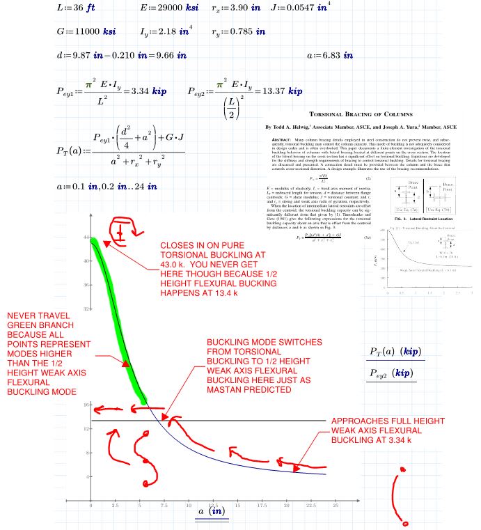
If you're saying that a bifurcation model should behave as you've described, then color me unconvinced. Are you able to prove your assertion in any way other than FEM runs? I was able to corroborate my stance almost perfectly using hand calcs based on a paper by Helwig & Yura on the subject. See the attached PDF which contains the calcs and clips from the paper (copyrighted or I'd share it all). As the Mastan model predicted, the increasing monotonic lateral torsional buckling curve never see its peak value because you hit the S-shaped, weak axis buckling failure load at about 1/3 that. Whether or not this is the case, and the extent to which this is the case, is a function of the ratios of Iy, Cw, and J for a give section.

c01_nkjesc.jpg
 
We've been through this Kookt. Can we not go over the same territory? I'm ducking out again.

One screenshot won't show anything stop demanding something that is impractical to give. Do you own research I've held you hand on this one enough. The hand calcs you have described are a simplification. You half height weak axis flexural bucking isn't a straight line when it comes to a point restraint offset from the central axis.

You can't seem to get your head around the reality that our simplifications of buckling into minor-axis, major axis, LTB, etc are just that simplifications. Your calculations above just looks at two distinct buckling modes rather than considering the reality that they both can and DO occur together.
 
human909 said:
I'm ducking out again.

As you wish.

human909 said:
The hand calcs you have described are a simplification.

Yes, they are. Simplifying things such that hand calcs may be used to validate sophisticated models is an important part of engineering with software. I'll certainly not apologize for doing that.
 
Human, regarding the beam cases, could you possibly respond to my 5 Dec 19 23:32 question.

I.e. does your software agree the AS4100 L-restraint provisions can be unconservative?
 
If I understand Human909's work correctly, his Nastran capacity for the W10x12 is about double my Mastan capacity. I wasn't entirely sure what RFreund had done with his presentation of AS4100 as an ALR so that might be worth double checking. I had assumed his stuff was:

[AS4100 design capacity with bracing starting at 8' / max moment from 12k point load]

RFreund said:
AS4100 using inflection point and alpha_m: ALR = 0.547

31.2 k-ft

Human909 said:
And here is my first mode for the W10x12. The load factor is 0.375

20.3 k-ft

KootK said:
Run #1: ALR = 0.19055; L-braces everywhere.

10.2 k-ft
 
Tomfh said:
does your software agree the AS4100 L-restraint provisions can be unconservative
Hey Tom. Sorry for missing your question. Yes I agree and so does my software that AS4100 can be unconservative with regard to L restraints. To elaborate:


I concurr with Kootks numbers above.

My AS4100 calculated figure is 0.56. (Im not using inflection point but using all L braces at compression flange as per code.) AS4100, comprehensively misses the mark when we have two buckling analysis packages suggesting this overestimates capacity by 33-66%! And while we can and have debated modelling techniques, I don't believe there has been any suggestion that our buckling analysis techniques have been UNDERESTIMATING the real buckling capacity.

Thus I think the agreement is that AS4100 significantly not conservative for the scenarion presented. This doesn't look great, for AS4100. But there are a couple of caveats:
-Real world lateral braces are not point restrains and provide some minor rotational restraint which is quite influential
-Real world beams have some minor rotaional restrain in the minor axis, again this can be quite influential unless the beam is very long. {See edit}


(I have another model running and will update this post once complete)

EDIT:

My other model didn't work out. I tried to contive a scenario of self weight buckling showing AS4100 being conservative, but no such luck. It would seem that you need to got to worst case sceanios to get AS4100 to fail. ie deep, lightweight beams centrally loaded. In Australia beams as deep and light as W10x12 don't really exist. However that is hardly a good excuse.

One additional point. I added minor axis twist restraint to the W10x12 and while buckling load increase it still was below the capacity of AS4100.
 
Kootk said:
This one's for the AISC crowd.
Good stuff. Always good to know what's really going on.

Kootk said:
I wasn't entirely sure what RFreund had done with his presentation of AS4100 as an ALR so that might be worth double checking. I had assumed his stuff was:
Yes my ALR is the percent of the point load that causes a moment equal to the plastic moment strength (i.e. 12kips). I used the unbraced length as the inflection point (assuming that an L-restraint was placed at the L-Restraint).

human909 said:
Hey Tom. Sorry for missing your question. Yes I agree and so does my software that AS4100 can be unconservative with regard to L restraints. To elaborate:
Thanks for the follow up, I was also curious.

Does this revelation mean that just about every continuous beam system that lacks a bottom flange brace would be an issue?

EIT
 
Thanks for the response, human909. Everyone seems to be in agreement here. If anyone has a contrary view, save us!


Rfreund said:
Does this revelation mean that just about every continuous beam system that lacks a bottom flange brace would be an issue?

In many situations it won’t matter. Eg the simply supported case. But in continuous beams where the unbraced flange goes into compression it seems it could be an issue.

People mention that in the real world you get twist restraint at purlins/joists. No doubt you do, but it’s a worry if people (myself included) are inadvertently relying on some P restraint to get over the line. If you actually need some rotational restraint for the design to work then AS4100 shouldn’t say be saying L restraints are sufficient.

I’m very curious as to the range of scenarios where this could be an issue. At present I’m unclear as to how big this hole really is.
 
RFreund said:
Yes my ALR is the percent of the point load that causes a moment equal to the plastic moment strength (i.e. 12kips).

I used Celt83's spreadsheet to double check the W10x12 example as it's mission critical. It revises the moment that I based on your estimate a bit. Links to the spreadsheets are included if anyone wants to review them.

Nastran

20.3 k-ft

Mastan

10.2 k-ft

AS4100 @ L = 9' (Most unconservative use of segment definition as example intended to exploit)

35.7 k-ft Link

AS4100 @ L = 13.5' (Most conservative use of segment definition and as Aussies typically apply this by the sound of it.

15.5 k-ft Link

In practice, an inflection point is rarely going to land right at a brace location and you'd be somewhere between the extremes of the two AS4100 numbers

RFreund said:
Does this revelation mean that just about every continuous beam system that lacks a bottom flange brace would be an issue?

Meh. It's worth keeping in mind that I went out of my way to choose an example that would tease the issue out including:

1) High Ix/Iy ratio. That said, in the US, these often are the "preferred" or lightest weight sections.

2) A moment diagram meant to maximize bottom flange compression effects while still retaining the top flange as the critical flange over much of the length. As discussed just a few posts back (Celt83), just the switch from a point load to a distributed load improved the amount of end moment developed by 24% in Mastan.

3) Locating an L-brace right at an inflection point to force an AS4100 evaluation over the shortest possible segment length and maximize the returned capacity.

So, yeah, there are a lot reasons to think that your average, moment reversal beam in practice would be better off than this thread would suggest. It's like Tomfh mentioned for accidental bonus restraint though: we don't normally want to be placing great reliance on things that we don't control and/or cannot quantify reliably.

 
Yesterday I was looking to contrive an example where a beam would buckle under self weight with an AU member size. I just thought that self weight failure is a more interesting example.

EG: 46m 610UB101 with single lateral brace at the top flange in the centre
LOAD FACTORS:
AS4100: 1.01 (PLP & FLF)
NASTRAN: 0.753 (PLP) (No minor axis or flange restraint at ends, no twist restraint at lateral brace)
NASTRAN: 0.757 (PLP) (No minor axis or flange restraint at ends, twist restraint at lateral brace)
NASTRAN: 2.59 (FLF) (Full end restraint, twist restraint at lateral brace)

A few points:
-An Australian beam failing comprehensively
-Twist restrain at the flange can sometimes offer very little increase in capacity (this aspect is something I've been highlighting as a mitigating factor)
-An unrestrained minor axis is highly influential on buckling behaviour for a small number of lateral restrains (in this case 1), though AS4100 doesn't explicitly take this into account (Does AISC??)
-An unrestrained minor axis is unrealistic in a single span scenario, though can be quite realistic in a countinuous member scenario with a pinned column support underneath.

 
Status
Not open for further replies.

Part and Inventory Search

Sponsor