Continue to Site

Eng-Tips is the largest engineering community on the Internet

Intelligent Work Forums for Engineering Professionals

  • Congratulations KootK on being selected by the Eng-Tips community for having the most helpful posts in the forums last week. Way to Go!

Rafter without fly brace? 22

Status
Not open for further replies.

fourpm

Industrial
Oct 12, 2019
13
I am designing rafters to AS4100 and wondering what if I don't use fly brace. I understand that with fly brace it will give you full restraint. But if I don't use fly brace, will the purlin above be considered as lateral restraint for rafter under uplift? If so. can I take the purlin spacing as segment and the only factor that changes without fly brace is kt?
I have the same question when it comes the continuous steel floor beam design where Z/C floor joints sit on top of the beam. What segment should I take for the beam near the support? Can I take the floor joists spacing as segment with lateral restraint? Can anyone give me some examples? I have read some manuals but the examples they have are simply supported beams only. Thank you.
 
Replies continue below

Recommended for you

A happy post-Thanksgiving to all of my non-Canadian cohorts.

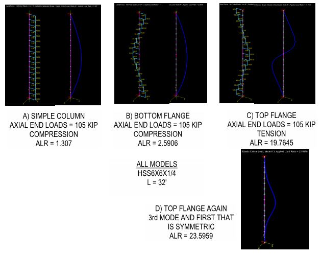
I prepared the attached PDF to answer some questions that I've been interested in since Celt83 conducted a similar exercise. And I thought that they might be of interest to the group. Basically, I wanted to study the flanges of our W27x84 test beam as isolated compression members to get a sense for how the behavior and capacity of such members would be affected by a compression distribution that varies over the length of the member and is substantially tension over segments of the member.

My observations:

1) In many important respects, a beam cannot be considered to be merely an assembly of independent axially loaded fanged. No surprise there. This representation completely ignores that fact that both flanges are continuously braced, to a degree, by the St.Venant torsional stiffness of the beam. That makes a big difference and must be remembered.

2) Relative to a classic, Euler column, a column loaded like a beam bottom flange would have about double the capacity.

3) A column loaded like a beam bottom flange still buckles over its entire length, as our LTB models have suggested.

4) Relative to a classic, Euler column, a column loaded like a beam top flange would have about fifteen times the capacity. Clearly, a flange with its compression field located at its ends (bottom flange) is much more unstable than a flange with it's compression field located at its middle (top flange).

5) I've come to view LTB, at least for our test case, as something like:

a) the bottom flange initiates some twist.

b) with some twist in play, some of the applied load becomes a weak axis load on the beam and initiates some sway.

Obviously, these are two actions occurring in tandem rather than sequentially.


c01_spfwan.jpg
 
Yep, and D shows the effect of fixing weak axis bending. It largely neuters the bottom flange compression near the supports.
 
Tomfh said:
Yep, and D shows the effect of fixing weak axis bending.

Right. And that takes me back to some comments that Human909 made some time ago. I'd meant to comment on them then but things were moving fast and it got lost in the shuffle. I believe that his points were:

1) Human909 pointed out that, in many cases where you would have end moments develop, you would also naturally tend to have some degree of weak axis restraint. And that's true of course. I did my best to steer the conversation towards beams without weak axis end restraints for two reasons however:

a) AISC and most of the reference cases are built around members without the weak axis end restraint. So in the interest of comparing similar things, I thought it best to stick to beam ends that were pinned with respect to weak axis flexure.

b) In the literature, when they discuss interaction buckling, they're always careful to point out that the effect of considering weak axis behavior of adjacent spans isn't always your friend. Sometimes it does provide significant restraint to the span being studied and, naturally, will improve capacity in those cases. Other times, the adjacent span may actually be encouraging buckling in the span being studied rather than restraining. In that sense, even going with beam ends as weak axis pinned isn't always a conservative assumption. But, then, one has to put a pin in it someplace and move on. So we typically put the pin in the neutral, pinned ends assumption.

2) Human909 made note of the fact that, when beam ends were fixed about the weak axis, that made for a 100% increase in capacity. In examining the case below, that observation checks out. In going from pinned to fixed ends, you're basically going from k = 1.0 to k = 0.5 on the "flange as column" model. And while we don't see a 400% improvement in capacity, a large bump makes sense.

c02_vjgd7g.png
 
Kootk said:
A happy post-Thanksgiving to all of my non-Canadian cohorts.
Thanks. And I'm thankful that the pace has slowed down here so it hasn't been too difficult to catch up.

Getting back to verifying the mastan results with the modified C.b factor...
Kootk said:
W10x12
Mid-span point load = 12 kip (full section yield at 11.7k)
Span = 36'
AS4100 using inflection point and alpha_m: ALR = 0.547
AISC with normal cb: ALR = 0.1424
AISC with modified cb: ALR = 0.2715
Mastan (per Kootk) = 0.1906

What if we use a uniform load of 500 plf (give same end moment)
AS4100 using inflection point and alpha_m: ALR = 0.7276
AISC with normal cb: ALR = 0.1763
AISC with modified cb: ALR = 0.2222
Mastan (per Kootk) = ????


EIT
 
Please refer to the snips below and the attached PDF of the same.

I also wanted to explore a bit more the business of L-retraints (lateral only / one flange) being taken as equivalent to F-restraints (lateral restraint + cross section rotational restraint). A brief summary:

1) A while back, Steveh49 dropped on us the extinction level bombshell that AS4100 considers L-restraints equivalent to F-restraints in many cases. I don't think that I was alone in finding that shocking.

2) I came to a revelation of my own that, in fact, both AISC and AS4100 routinely assume that rotational restraint exists where only an L-brace is present. The ubiquitous case of that being simple span beams with intermediate, lateral braces on the top flange. So assuming rotational bracing at locations only having lateral bracing isn't an outlier thing, it's an all the time, everywhere thing. And it needs to be explained in that context.

3) In a post dated [27 Nov 19 01:59], tomfh and I explored how this applied to simple span beams and came to the conclusion that, indeed, it was appropriate to consider L-braces as F-braces for such cases.

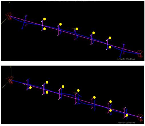
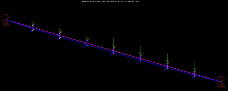
Where I'm at now is that, if L-bracing is going to be effectively taken as F-bracing in some situations but not others, then I'd like to know the rules of the road. When is it okay and when is it not? To that end, I've studied the cases below. This is our usual W27x84 with the center point load. I've placed F-bracing at the inflection points and L-bracing in between. From the perspective of both AS4100 and AISC, the span between the IP F-bracings would be treated as an independent design segment within which the L-bracees could be assumed to prevent cross section rotation. So the point of the exercise, then, has been to assess the truthiness of that claim.

CASE 1

Here, at an ALR = 8.3991 and no bracing at the 1/4 points, it would appear that the L-braces are not effective rotational restraints. That said:

a) It appears to me that it is the buckling of the the spans to the left and right of the IP F-braces that is encouraging the bottom flange "kick out" between the IP F-braces.

b) To an extent I think that one can say that, if a buckling mode that would induce rotation at the L-braces occurs at a wildly high ALR, that's not really a repudiation of the notion that such L-braces are effectively F-braces.

CASE 2

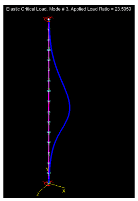
At an ALR = 24.1222, this is the same as case one but with the addition of bottom flange bracing at the 1/8 th points. As can be seen by the snaking buckled shape between IP L-braces, and the relative absence of cross sectional rotation within that segment, this removes the tendency for twist between the IP F-braces entirely and restores that segment to a state where the assumption that the L-braces are effective F-braces would be appropriate. So a nice benefit of case two is that the end segments no longer buckle and encourage section rotation between IP F-braces. I would argue, however, that this benefit could be gained in two ways:

a) Provide actual bottom flange L-braces at the 1/8 th points as shown or;

b) Simply design the the segments left and right of the IP F-braces such that they don't buckle without the 1/8 th point bracing.

I feel that this is an important equivalency.

The Proposed Rules of the Road for L-braces Equivalent to F-braces

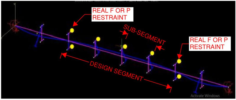
Speaking the parlance of AS4100, and being mindful of the AS4100 distinction between "segment" and "sub-segment", I tentatively propose that intermediate L-braces may be assumed to be equivalent to F-braces within a design segment, and therefore taken as forming sub-segments, when:

1) The design segment being studied is itself bounded on each end by F-braces (real, physical ones).

2) The design segments either side of the segment being studied, if present, have been properly designed to preclude buckling there.

3) A "compression flange" shall be defined as any flange experiencing compression anywhere within the design segment being studied, regardless of whether or not that flange would experience compression at the particular location of any given L-brace.

4) Any design segment may have as many as two compression flanges, as dictated by loading conditions. In such cases, both flanges must be independently stabilized laterally and independently evaluated for stability.

c01_cowem4.jpg


c01_aolzcg.jpg


Kootk said:
1) A while back, Steveh49 dropped on us the extinction level bombshell that AS4100 considers L-restraints equivalent to F-restraints in many cases. I don't think that I was alone in finding that shocking.

2) I came to a revelation of my own that, in fact, both AISC and AS4100 routinely assume that rotational restraint exists where only an L-brace is present.

I don’t quite agree with this. The codes (in particular AS4100) do not assume rotational restraint exists a L. AS4100 is quite explicit that no rotational restraint exists at L restraint. That’s the key feature of an L (as opposed to an F or P) - there is no rotational restraint. So the codes are not saying the rotational restraint is equivalent, they are saying it is equivalent level of buckling performance. They say you don’t need the full restraint to stabilise the cross section - and thus it is considered redundant to go from
L to F. They assume it won’t move if you stabilise the critical flange. Hence “equivalent” performance, even though they’re not actually equivalent.

These buckling runs you are doing suggest that is a a faulty assumption, in which case modified rules like you suggest are perhaps appropriate.
 
Tomfh said:
I don’t quite agree with this.

Great. I would very much like for us to come to complete agreement on this aspect of things before moving on to other things. Moreover, I feel that's entirely possible given that I think we're saying identical things, just in different, and perhaps not perfectly precise, ways.

Tomfh said:
..they are saying it is equivalent level of buckling performance. They say you don’t need the full restraint to stabilise the cross section...

I agree with that 100% and it is, in fact, what I had intended to say myself. Below, I'm going to elaborate at length on what I feel are the important similarities and differences between real, physical F-restraints and the equivalent, faux F-restraints that L-restraints are sometimes assumed to create. Please review it and let me know:

a) If you disagree with any of my assertions and/or;

b) If you feel that I've omitted anything important.

In this way, we can isolate the points of true disagreement, if any, and deal with them in a targeted fashion.

Comparing and Contrasting Real F-braces (RFB's) with Fuax-F-braces (FFB's)

1) An FFB is not as rotationally stiff as an RFB.

2) An FFB is not as rotationally strong as an RFB

3) Because of #1 and #2, an FFB cannot be assumed to define the end points of a design segment as an RFB can.

4) Within a range of applicability, an FFB can create a condition wherein a design segment may be subdivided into sub-segments for design purposes such that:

a) the end points of such sub-segments may be taken to be the locations of the FFB's and;

b) for the purpose of stability design, designers may assume that LTB buckling modes associated with cross sectional rotation at the ends of such sub-segments is precluded.

5) Where conditions are met such that an L-brace may be assumed to serve as an FFB, it is understood that no significant cross sectional rotation is expected to occur at the locations of the FFB's prior to the sub-segments between them reaching a point of LTB instability between the FFB's.

Now for the bar exam...
 
RFreund said:
What if we use a uniform load of 500 plf (give same end moment)
AS4100 using inflection point and alpha_m: ALR = 0.7276
AISC with normal cb: ALR = 0.1763
AISC with modified cb: ALR = 0.2222
Mastan (per Kootk) = 0.19367

Done. A couple of things to note:

1) While Mastan does have a utility for uniform load, to my knowledge, there is no way to apply a uniform load to a member at any location other than the shear center. Rather than getting fancy with more faux members with difficult to predict behaviors, I just discretized the uniform load as serious of equivalent point loads at the 1/8th points. [500 plf * 36 ft / 7 = 2.571 k] each. Hopefully this is sufficient for your purposes.

2) I don't know about you but I'd expected the switch from a point load to a uniform load to have more impact than it seems to have. Having pondered this a bit, my explanation for this is:

a) LTB for this situation is mostly the story of the bottom flange kicking out laterally.

b) The tendency for the bottom flange to kick out laterally is most greatly affected by the compression force delivered to the ends of the bottom flange.

b) End moments, and therefore the compression force delivered to the ends of the bottom flange, are pretty much the same for both cases even though the lateral distribution of applied load is quite different.

RFreund said:
And I'm thankful that the pace has slowed down here so it hasn't been too difficult to catch up.

Perhaps we should observe a self imposed limit of one post per person per day going forward. Except for me, I get five.

c01_medm3i.jpg
 
Kootk,

Yes I agree with your points 1-4

If the cross section doesn't move or rotate at the L restraint (i.e. forms buckling nodal point) then it should be equivalent in performance to an F restraint, e.g. what happens in the simply supported cases.

I would love if there was a deeper rationale than these isolated cases for AS4100's general advice to treat Ls as Fs, but it doesn't seem to be the case. :(
 
KootK,
What is the load level in those analyses? Does ALR=1.0 correspond to the bending moment at elastic buckling equalling plastic section capacity?

Your rules are how I had understood AISC 360 works based on discussion in this topic. Is that the case or are there differences?
 
steveh49 said:
Does ALR=1.0 correspond to the bending moment at elastic buckling equalling plastic section capacity?

Yes, roughly speaking, that is how the loads have been chosen in most cases. I always round a little one way or the other so that I've got sensible numbers to enter in to the models. That said, all that really matters is the load at which buckling occurs. I really only chose to input a load that would approximately produce plastic bending moments so that:

1) There would be some meaningful benchmark and;

2) We'd be dealing with numbers between 0.1 and 100 which feel better to humans than, say. 0.00000052147 which would be equally valid.

steveh49 said:
What is the load level in those analyses?

Always [Buckling Load = ALR x applied load]. I believe that I introduced the applied load level with the first instance of each geometrically different beam model. For all of the 32' W27x84 models, the load was 250k in the middle. For Tomfh's 36' W10x12 models, the load was 12k in the middle. If you're unable to decipher the load level for a particular run, let me know and I'll chace it down.

steveh49 said:
Your rules are how I had understood AISC 360 works based on discussion in this topic. Is that the case or are there differences?

That is the case. I was, however, intentionally avoiding that head to head comparison for the time being for fear that it would be somewhat inflammatory. Because I am a ridiculous glutton for punishment, I am eventually going to take another stab at rewriting/reinterpreting AS4100 in a way that I feel would resolve the discrepancies that now seem manifest. At this point, I feel that an error in the writing of AS4100 is at least as likely as:

3) All of he modelling work being wrong (certainly possible) or;

4) Trahair and the rest of genius kind actually botching the theory.

And likely or not, what does it hurt to run a mental, "what if" experiment of this sort for sport?

One of the outcomes of that hypothetical exercise will be that AS4100 would effectively collapse into being identical to AISC save for AS4100's more advanced consideration of imperfections. I'll in no way be insinuating that AS4100's only path to righteousness is to get in line behind AISC however. Rather, I'll make the argument that parity between the codes ought to be the default expectation given that:

5) This stuff is, at it's core, just Newtonian physics in a common gravitational field and;

6) Research is constantly shared across borders so cross pollination abounds.


Kootk said:
At this point, I feel that an error in the writing of AS4100 is at least as likely as:

I consider that very unlikely. AS4100 surely intends for L to count as buckling node?

In my view the most likely option is there is a hole in the AS4100 theory, and that L restraints ought not be considered buckling nodal points, but in the real world L restraints actually function as P or F restraints, which significantly inhibits buckling, plus we rarely see ultimate design loads.

The modelling being wrong is also a real possibility. Maybe MASTAN can't do it properly. Human's NASTRAN models certainly seemed more inclined to produce buckle modes more in keeping with AS4100 assumptions.
 
steveh49 said:
Your rules are how I had understood AISC 360 works based on discussion in this topic. Is that the case or are there differences?

I'll also add that that is how AISC works only because that is, for reasons not known to me, how AISC is applied. As others have pointed out, based on syntax alone and in he absence of any ancillary documents, AISC reads as pretty much identical to AS4100.

AISC practitioner interpretation has broken in a more conservative direction which has led to AISC seeming to not have an issue with overestimating capacities. Still:

1) The AISC standard does not explicitly state the "rules" in the way that I have proposed and, more importantly;

2) The AISC standard certainly does not expound upon the reasoning for the rules.

In these respects, I feel that AISC could have done a much better job of fully conveying the nuances of its approach to LTB design.
 
Tomfh said:
I consider that very unlikely.

Shocking.

Tomfh said:
AS4100 surely intends for L to count as buckling node?

Agreed, under the right conditions. It is in the expression off those conditions that I speculate that an error might exist.

[s said:
Human909[/s]Tomfh]Human's NASTRAN models certainly seemed more inclined to produce buckle modes more in keeping with AS4100 assumptions

I disagree. My perception was that the NASTRAN models were plagued with modelling errors for much of the thread and, once those errors were resolved, the results began to align with the Mastan results and tell a similar story.

Tomfh said:
Maybe MASTAN can't do it properly.

Maybe not. Or, more likely, maybe KootK can't do Mastan properly. Still, I think that the fact that the Mastan results and the AISC results are fairly well aligned adds some measure of credibility to the Mastan results.
 
Kootk said:
I disagree. My perception was that the NASTRAN models were plagued with modelling errors for much of the thread and, once those errors were resolved, the results began to align with the Mastan results and tell a similar story.

I was referring to a few of the models showed short length bottom flange buckles between L restraints. Maybe these are due to modelling inconsistencies/errors like you suggest. Nonetheless I think it's worth keeping the NASTRAN short buckle results in mind. I don't believe it should be written off. Maybe NASTRAN is seeing something that MASTAN isn't.

Kootk said:
Agreed, under the right conditions. It is in the expression off those conditions that I speculate that an error might exist.

AS4100 is pretty clear on it - a lateral restraint attached to the flange which buckles the furthest (5.5.1) or attached to a compression flange (5.5.2) counts as an L, which defines buckling length.

Kootk said:
Maybe not. Or, more likely, maybe KootK can't do Mastan properly. Still, I think that the fact that the Mastan results and the AISC results are fairly well aligned adds some measure of credibility to the Mastan results.

The MASTAN results appear credible to me.
 
KootK said:
My perception was that the NASTRAN models were plagued with modelling errors for much of the thread and, once those errors were resolved, the results began to align with the Mastan results and tell a similar story.
Please avoid misquoting...

But you comments here are not really that accurate. This "plague" of "modelling errors" were models of imperfect pinned connections. They were removed to get alignment with the perfect pins being used to give the Mastan results. The reality is that REAL WORLD connections are not perfect pins. Real world connections almost always have a non negligible degree of stiffness and this stiffness is often enough to significantly change the buckling behaviour.

Also I wouldn't put the blame on NASTRAN, I'd put the blame on the user (myself) or the problem description (perfect pin connections).

I am currently of the opinion that AS4100 could be unconservative in some situations. The simple logical extension of a hypothetical infinitly long beam with L restrainst all along it having appropriate twist restraint is evidence of AS4100s failings. Whether this translates readily to realistic scenarios hasn't been adequately fleshed out.
 
Human said:
The reality is that REAL WORLD connections are not perfect pins. Real world connections almost always have a non negligible degree of stiffness and this stiffness is often enough to significantly change the buckling behaviour.

That’s correct. But it is a problem if AS4100 is actually reliant upon rotational restraint occurring at L restraints. The whole premise of L restraint is no rotational restraint.

If I actually need some rotational stiffness at L restraints in order for AS4100 to work then I want to know about it.

And we don’t need infinite long beam for this to be a problem. These buckling results are perfectly ordinary span sizes.
 
human909 said:
Please avoid misquoting...

How? It's not as though I misquote on purpose. I exert more quality control in my posts than most here on Eng-Tips but, in a 500 post thread, a couple are gonna slip past the goalie.

human909 said:
The reality is that REAL WORLD connections are not perfect pins.

I addressed that pretty thoroughly in my first post today. Things do move pretty fast here though so I'd not blame you if you'd missed that one.

KootK said:
Right. And that takes me back to some comments that Human909 made some time ago. I'd meant to comment on them then but things were moving fast and it got lost in the shuffle. I believe that his points were:

1) Human909 pointed out that, in many cases where you would have end moments develop, you would also naturally tend to have some degree of weak axis restraint. And that's true of course. I did my best to steer the conversation towards beams without weak axis end restraints for two reasons however:

a) AISC and most of the reference cases are built around members without the weak axis end restraint. So in the interest of comparing similar things, I thought it best to stick to beam ends that were pinned with respect to weak axis flexure.

b) In the literature, when they discuss interaction buckling, they're always careful to point out that the effect of considering weak axis behavior of adjacent spans isn't always your friend. Sometimes it does provide significant restraint to the span being studied and, naturally, will improve capacity in those cases. Other times, the adjacent span may actually be encouraging buckling in the span being studied rather than restraining. In that sense, even going with beam ends as weak axis pinned isn't always a conservative assumption. But, then, one has to put a pin in it someplace and move on. So we typically put the pin in the neutral, pinned ends assumption.

human909 said:
Also I wouldn't put the blame on NASTRAN, I'd put the blame on the user (myself) or the problem description (perfect pin connections).

It was always my intent to assign any blame, if you want to call it that, as [100% Human909; 0% NASTRAN]. I intentionally didn't call you out by name when critiquing the NASTRAN models because I felt that it was unnecessary to do so and would be more tactful if I did not. I was trying to be polite and conciliatory within the limited range of my people skills.
 
Tomfh said:
Nonetheless I think it's worth keeping the NASTRAN short buckle results in mind. I don't believe it should be written off. Maybe NASTRAN is seeing something that MASTAN isn't.

Abso-friggin-lutely the Nastran results should not be written off.

KootK said:
Having a surprising result confirmed by two independent modelers, using two different software packages, and coming from two different fundamental perspectives was invaluable with respect to establishing credibility for the results.

The situation with the modelling, unfortunately, unfolded like this:

1) Human909 did a lot of modelling before I started.

2) I did a lot of modelling after Human909 stopped.

3) Due to the minimal overlap, Human909 and I only ever ran the same model once and the result, according to Human hisself, was:

Human909 said:
Kootk (1)
Human909 (0)

Of course one data point is no trend. If there is any doubt that a NASTRAN model would fail to confirm the results of one of my MASTAN models, I propose this:

1) Let's identify the model to be challenged.

2) Let's have human909 replicate my MASTAN model in NASTRAN.

3) Human and I will compare deflected shapes, weak axis bending moments, shear diagrams... whatever, until we get our models to agree.

This is, I submit, the rational thing to do when you have access to two fancy software packages. Make 'em fight it out!
 
Tomfh said:
AS4100 is pretty clear on it - a lateral restraint attached to the flange which buckles the furthest (5.5.1) or attached to a compression flange (5.5.2) counts as an L, which defines buckling length.

AS4100 is pretty clear on it. However, if there are errors in AS4100, then AS4100 may be pretty clear on something that is incorrect or was never intended. And that's kind of my point.

I think that you're jumping the gun on your critique of my stuff here given that I haven't actually made my proper pitch yet. Steveh49 kind of tricked me into showing my cards before I'd wanted to. So how about this:

a) Put a pin in your critique for the time being.

b) When I've said my piece, I'll invite you to critique what I've tabled in it's entirety.

I'll get it done by Sunday night.
 
Status
Not open for further replies.

Part and Inventory Search

Sponsor