Continue to Site

Eng-Tips is the largest engineering community on the Internet

Intelligent Work Forums for Engineering Professionals

  • Congratulations KootK on being selected by the Eng-Tips community for having the most helpful posts in the forums last week. Way to Go!

Rafter without fly brace? 22

Status
Not open for further replies.

fourpm

Industrial
Oct 12, 2019
13
I am designing rafters to AS4100 and wondering what if I don't use fly brace. I understand that with fly brace it will give you full restraint. But if I don't use fly brace, will the purlin above be considered as lateral restraint for rafter under uplift? If so. can I take the purlin spacing as segment and the only factor that changes without fly brace is kt?
I have the same question when it comes the continuous steel floor beam design where Z/C floor joints sit on top of the beam. What segment should I take for the beam near the support? Can I take the floor joists spacing as segment with lateral restraint? Can anyone give me some examples? I have read some manuals but the examples they have are simply supported beams only. Thank you.
 
Replies continue below

Recommended for you

@Agent666 I was reviewing some of the curves that you posted. It looks like they compare moment capacity to unbraced length which I suspect the AS4100 will be more conservative due to the equation. However, I assume they are both using the same unbraced length in this comparison. In the current situation we are using different unbraced lengths as directed by the code. So referring back to those curves doesn't seem to help in this situation.

EIT
 
RFreund said:
Is this in AISC? Or where is the this from?

It's from the Yura article that you've probably heard referenced repeatedly. I posted a copy a zillion posts ago but I'll save you the trouble of fishing for that and just post another copy here. It's definitely worth a front to back read when you've got the time. AISC specific although, as you'd expect, rooted in first principle stuff.

RFreund said:
I've always understood that you can either restrain the compression flange from lateral movement or prevent twist.

Agreed with the understanding that preventing twist can, in many ways, just be envisioned as another, indirect way to restrain the compression flange laterally. The glorious reach around.

RFreund said:
Which in the fixed end beam the bottom flange is only braced against lateral movement at supports.

Agreed. The fundamental difference between AISC and AS4100 seems to boil down to just this: AS4100 lets your brace a flange with a lateral only brace on the other flange so long as that other flange is in compression at the location of the brace. With AISC, a flange can only be braced by a lateral only brace if that brace is attached to the flange intended to be braced. Or, at the least, this seem to be how it's applied. All of this, of course, harkens back to the recent "epiphany" that AS4100 treats L-Restraints as, effectively, F-restraints in many situations.


 https://files.engineering.com/getfile.aspx?folder=c2a6be3a-6b6a-41ea-b643-f6682c0450d7&file=buckling-of-beams-with-inflection-points.pdf
Kootk said:
We've seen the wizard behind the curtain now and the magic is not what what it was purported to be.
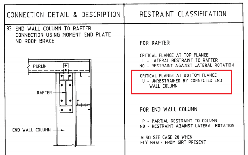
Well I'm thoroughly confused by this diagram from the 'wizard'.
temp_y3gmpj.png

Wait. What?

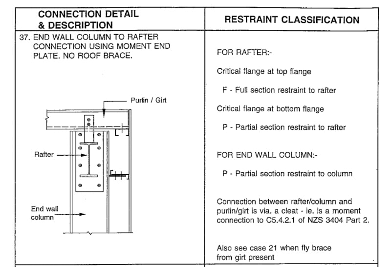
Is this diagram suggesting that the the rafter is unrestrained by a moment end plate connected to a column. In what way is that not a flange restraint of any nature?
 
Maybe it’s intended to cover flexible columns? Seems a bit harsh though.
 
I considered that. Though even with sway columns and a flexible web your still would get the beam flanges restrained for buckling purposes. I'd hope my columms can provide more lateral restraint to a beam than a random purlin!
 
kootk said:
Hold the phone... are you saying that, using the buckling analysis option, you'd still do the AS4100 post-processing segmentally? Even though your FEM model would show you something completely different (sketch below)? I had not anticipated that and it strikes me as a terribly inconsistent mix-match of the stories being told. Consider the following as it would pertain to the 70' beam example:

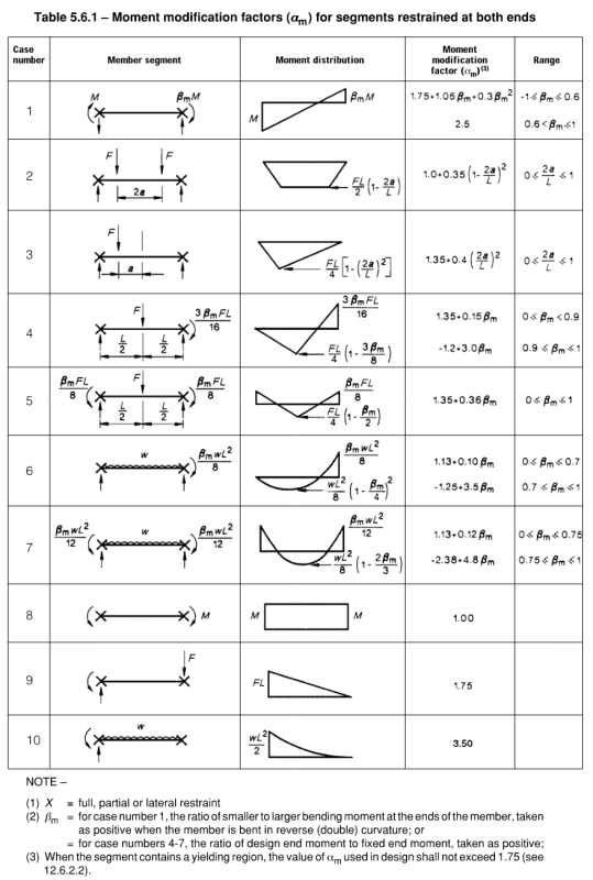
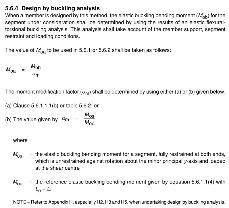
Yes. You need to determine alpha_m for critical segment, so you can divide it out from the maximum moment to determine M_oa for your scenario (this is the reflection of theoretical L_e). Then you use this to determine alpha_s. Read 5.6.4, you can either use the table 5.6.1 to determine alpha_m or determine M_os and use the equation noted to determine alpha_m (keeping in mind alpha_m from tables are typically curve fit).

How many times do I need to explain this... serious question? Getting the mastan2 result is half of the job. Comparing anything but the end design capacity is flawed in my view, the buckling moment x alpha_m from a buckling analysis is not an upper bound indicator of capacity. Coming at this from the other direction because I'm not terribly familiar with aisc, what exactly are people reporting when quoting aisc capacities, is it a moment based on F_e?

 
I think the question is whether it's correct to use alpha_m from the tables/equation using the AS4100 segment lengths when the buckling analysis doesn't match the hand-determined segments.

More generally, what if the restraints being relied on aren't in accordance with AS4100 F, P or L? Eg torsion cross-frames in bridges or bottom flange L on a beam with low E*Iw (K=0.1 so bottom flange L is as good as top flange per earlier graph).

Is there some way to use buckling analysis without having to know the effective length beforehand?
 
Agent said:
Getting the mastan2 result is half of the job.

Could you show how doing the other half leads to a greater capacity?

I agree with Kookt here. The idealised buckling load shouldn’t be less than the predicted capacity. That kootk hasn’t done every step in the design chain doesn’t matter, as the steps reduce idealised capacity.

If we’re missing something please explain.


Alpham said:
I think the question is whether it's correct to use alpha_m from the tables/equation using the AS4100 segment lengths when the buckling analysis doesn't match the hand-determined segments.

AlphaM is just a kludge used to predict buckling load when it’s not the basic case of uniform moment. It’s of little relevance when you calculate buckling load directly. That’s why they get you divide by it if using the elastic buckling method - so it cancels out.
 
Edit, this was in reply to steveh49s post above (Tom snuck a couple of replies in there)

Not sure to be honest. The real world scenarios I've used it are when you aren't sure where you fit into the stiff or flexible realm for restraint stiffness and whether that has any real world effect on the buckling. But you still have a discrete restraint provided of questionable stiffness that is adequate for the 2.5% restraint forces. So you can at least apply the segmentalised way of applying 5.6.4 in this scenario based on exercising some judgement.

As for when you have some kooky way of restraining it in a way that isn't in the spirit of the discrete L/P/F type restraints to non compression flanges then you're on your own there.


I never said applying the provisions to determine the design capacity leads to a greater capacity than the buckling moment value, the design capacity is going to be different. But how much different is highly dependant on removing the alpha_m and getting M_oa, then evaluating alpha_s, etc, etc.

By using the elastic buckling moment everyone's throwing around these values and comparing it for example to the spacegass checks or hand checks of design capacity when they aren't even comparing the same things. Buckling moment vs design capacities. Irrelevant comparison isn't it?
 
Alpha_m doesn't cancel though. You divide by it, do the nonlinear alpha_s calculation, then multiply by it.
 
It doesn’t make much difference. It more or less cancels out. It’s not the big deal you guys are saying.

It’s besides the point anyway, as the net result of the alpha and phi factors is a further REDUCTION in buckling load. It just makes it even worse.
 
Agent said:
Buckling moment vs design capacities. Irrelevant comparison isn't it?

Design capacity coming out higher than the unfactored buckling moment is not an irrelevant comparison.

It’d be like if your pinned column capacity is coming out higher than its Euler buckling load.
 
I'm going to walk through this to make sure I have this right. Thanks Agent666 for posting that Portal Frame design tips.

Design procedure:
Portal Frame Design Tips Seminar Proceedings aka GEN7001 said:
Rafters
Nominal Bending Capacity Mbx in Rafters
Simplified Procedure
NZS 3404 uses a semi-empirical equation to relate the nominal bending capacity Mbx to the elastic buckling
moment Mo and the section strength Msx, which for Universal and Welded Beams and Columns can be taken as
Zexfy. This philosophy uses a set of semi-empirical equations to relate the member strength to the plastic
moment and the elastic flexural torsional buckling moment

Mbx = alpha_m * alpha_s * M_sx < M_sx

M_sx = Section strength, Z_x * F_y

alpha_m = Moment modification factor (similar to C.b) this will increase your nominal moment capacity due to the moment distribution.
alpha_s = Slenderness reduction factor. This is a reduction factor which basically reduces your section moment strength based on the ratio of the elastic buckling strength to the section strength
AS4100_-_Slenderness_Reduction_c5vgwq.png


M_oa:GEN7001
AS4100_-_Elastic_Moment_M_o_-_description_v6ddhf.png


So M_o:
AS4100_-_Elastic_Moment_M_o_s5plnp.png

This is the elastic buckling moment which gives almost the exact same result as AISC (calculate elastic buckling stress in AISC then multiply by the section modulus) when using the same unbraced length

So M_o = M_oa.
This is only used to get alpha_s

Case 1: Unbraced length is full beam as it would be in AISC.
Assuming the unbraced length is long enough that LTB governs. AS4100 will give you a lower beam capacity than AISC because M.o is reduced by alpha_s. However, it seems like AS4100 says that the unbraced length is not the full length. But this gets wierder...

Case 2: Unbraced length at inflection point.
The unbraced length for AS4100 will be on the order of L/4. This will give you a much higher M_o and M.b even when multipled by alpha_s than the AISC fully unbraced beam length.

What should the unbraced length be according to AS4100?
GEN7001 said:
With Fly Bracing under Downward Load
The effect of the bottom flange near the columns being in compression due to gravity loads or other loading
should be considered even though most of the bottom flange of the rafter is in tension. A fly brace is
recommended near each knee and near the ridge to restrain the inside corners of the frame at kinks. A stiffener
between column flanges as indicated in Figure 4 effectively extends the bottom flange of the haunch to the
outside column flange which is restrained by girts. This effectively provides some restraint to the inside of the
knee. However, a fly brace near the knee is still recommended. With fly braces at least at the knees and the
ridge, the effective length will be 0.85 times the spacing between fly braces.

An alternative approach is to consider the rafter segment between the column and point of contraflexure if
accurately known, or nearest purlin beyond the inflection point. The inflection point is considered to be
unrestrained in determining the effective length. This approach is described in an example by Clifton,
Goodfellow and Carson (1989)

I can't seem to find this reference:
Clifton, G. C., Goodfellow, B., Carson, W., Notes Prepared for a Seminar on Economical Single Storey Design and
Construction, HERA Report R4-52, New Zealand Heavy Engineering Research Association, Manukau City, 1989

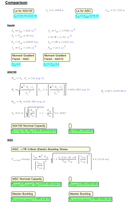
However, when looking at the bottom flange it sounds like you would take a L.e as the segment from column to the first purlin beyond the inflection point (worst case). And the end conditions of this segment are FU which gives KL = 1.0 (I think?)

Example:
Using KootK's W27x84 70' (21.3m) long beam example. Which has lateral braces on the top flange every 7' (2.1m). Fixed in the strong axis at both ends. Point load at center causes an inflection point between the 2nd and 3rd lateral brace (on the top flange). So at about 17.5' (5.33m).

So unbraced length choices:

Unbraced Length: 70' with C.b and alpha_m = 1.0
[ul]
[li]AISC M_nLTB (nominal lateral torsional buckling strength): 107 kip*ft (145kNm)[/li]
[li]AS4100 Mo: 107.5 kip*ft, alpha_s*M_s = 95.3 kip*ft[/li]
[li]Elastic buckling strength per Mastan2: 285kip*ft (386.5 kNm). This really isn't fair to compare to the above values as I haven't factored in C.b (alpha_m),b ut this is the highest value of moment capacity that can be achieved[/li]
[/ul]
*Note - Anything above 285kip*ft (386.5kN*m) can't be achieved. The beam will buckle prior to this moment
Updated with Cb and Alpha_m
C.b = 1.92
alpha_m: 1.7
ul]
[li]AISC M_nLTB: 206 kip*ft (280 kNm)[/li]
[li]AS4100 M_b = 162 kip*ft (220 kNm) [/li]
[/ul]

AS4100_A: 17.5'
[ul]
[li]AISC: Not allowed[/li]
[li]AS4100 Mo: 839.9 kip*ft (1138.7 kN*m), alpha_s*M_s = 468.8 kip*ft (635.6 kN*m)[/li]
[/ul]

AS4100_B: 21' (brace after inflection point)
[ul]
[li]AISC: Not allowed[/li]
[li]AS4100 Mo: 610 kip*ft (827 kN*m), alpha_s*M_s = 398.4 kip*ft (540 kN*m)[/li]
[/ul]

Calc Numbers:
AS4100_Comparison_Calc_for_21ft_nlrmn0.png


What is the equation for alpha_m? I can update these to include alpha_m and c.b factors.
- I will update these shortly
Side Comment: It would be great if we produced moment in Joules. Not sure why I find that so appealing. The whole energy thing I guess.

Hopefully I can get someone to double check this.

Takeaway
It seems like using the segment lengths (and please someone check these unbraced lengths for AS4100 cases) results in a beam capacity which cannot be achieved.

Edit 1: Formatting
Edit 2: Update alpha_s. This should multiply M_s not M_oa.

EIT
 
Hi RFreund, you're mixing a whole lot of ideas here that's going completely off target.

You're not multiplying alpha_s by Moa. You multiply the full plastic moment capacity (M_sx) by alpha_s x alpha_m x strength reduction factor. Moa is only required to calculate alpha_s. Otherwise it has no bearing on the capacity value or buckling values.

The moment coming out of the mastan2 buckling analysis is M_ob. This is M_oa x alpha_m. So to calculate alpha_s you need to determine alpha_m for the critical segment. Divide M_ob by alpha_m to get M_oa. Then work out alpha_s. Then work out M_bx the member moment capacity = phi x M_sx x alpha_m x alpha_s. If product of alpha_m and alpha_s is greater than 1 you have full lateral restraint, this means you can achieve the full plastic capacity of the beam. Phi is the strength reduction factor typically 0.9. M_sx is equal to plastic section modulus x yield strength.

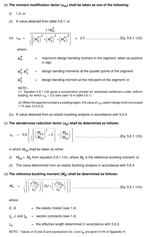
Generalised alpha_m equation is as follows and is worked out on a segment by segment basis (I'm sure it was posted earlier but is list in the 400 plus posts above, but good luck finding it!) :-
Capture_s3xvfb.png

There's also these equations for specific cases.
Capture1_om76jt.png

Alternatively you work it out from the process in CL5.6.4 which reads (this was the process being described in the SCNZ document I linked to):-
Capture2_ctnd3p.png


Hope that clears up the process for you?
 
Tom said:
Design capacity coming out higher than the unfactored buckling moment is not an irrelevant comparison.

The point is just getting people to compare apples with apples, not oranges with apples. If you are comparing a design capacity to a buckling moment they are two very different things and that comparison is irrelevant. If others find it relevant, then carry on.

As engineers, the final product is design capacity, comparing this is the measure of how one standard or method is gauged relative to another. The buckling moment is a theoretical buckling value, and as RFruend has noted its essentially the same formulation for all standards, because well its based on the solving of the underlying principles with whatever boundary conditions you impose.


me said:
Coming at this from the other direction because I'm not terribly familiar with aisc, what exactly are people reporting when quoting aisc capacities, is it a moment based on F_e?

Can someone please answer this for my own benefit in interpreting the apples from the oranges so I know what the AISC chaps are comparing to.
 
Status
Not open for further replies.

Part and Inventory Search

Sponsor