Continue to Site

Eng-Tips is the largest engineering community on the Internet

Intelligent Work Forums for Engineering Professionals

  • Congratulations KootK on being selected by the Eng-Tips community for having the most helpful posts in the forums last week. Way to Go!

Rafter without fly brace? 22

Status
Not open for further replies.

fourpm

Industrial
Oct 12, 2019
13
I am designing rafters to AS4100 and wondering what if I don't use fly brace. I understand that with fly brace it will give you full restraint. But if I don't use fly brace, will the purlin above be considered as lateral restraint for rafter under uplift? If so. can I take the purlin spacing as segment and the only factor that changes without fly brace is kt?
I have the same question when it comes the continuous steel floor beam design where Z/C floor joints sit on top of the beam. What segment should I take for the beam near the support? Can I take the floor joists spacing as segment with lateral restraint? Can anyone give me some examples? I have read some manuals but the examples they have are simply supported beams only. Thank you.
 
Replies continue below

Recommended for you

Holy crap steveh49!! Epiphany confirmed. Thank you so much. I'm actually getting closure on this which, after all this time, I'd all but given up on. I regret that I have but one star to give for your efforts.

c01_uy50e2.jpg
 
But in general how can L restraint be said to act as if fully restrained when Often see rotation at L restraints during buckling?

And likewise how can a lateral brace on non critical flange be said to act as if unrestrained when we see movement of the non critical flange in the unrestrained case? You see this even in a simple beam.
 
Well if you modelled an F (or P) restraint with a realistic rotational stiffness sufficient to restrain the section I'd bet you'd still see the same rotation.

Then the question applies to all restraints. The increase in capacity (but really buckling critical load) is linear with stiffness increase of the restraining system. Once you get over the theoretical stiffness you force a higher mode of buckling.

You can see this here to some degree in the example I came up with for axial loading. If I was to vary the stiffness of the left UC column and plot the buckling load it would hopefully follow the classic linear increase in buckling load up to a point where your higher mode buckling is fully developed. I haven't done this yet for a bending case, but it's on my list of things to do.

I also went through and did some comparisons to tabulated alpha_m values to highlight the fact that the elastic critical load analysis is outputting the theoretical alpha_m x M_o. Here


Tomfh said:
I may be misinterpreting you, but isn’t fixed major axis merely beam continuity (a perfectly feasible scenario), and isn’t the lack of minor axis restraint merely the absence of what the code refers to as lateral rotational restraint?
No you aren't misinterpreting me. I'll have to look into this. This connection doesn't seem in the spirit of a P restraint...

Tomfh said:
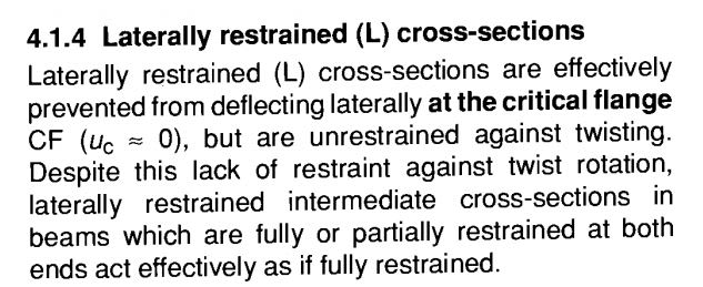
But in general how can L restraint be said to act as if fully restrained when we see often see rotation at L restraints during buckling?
I agree, it cannot be identical. In certain circumstances it's ability to prevent the first mode of buckling occuring could be identical which could be the basis for the claim that they act "effectively as if fully restrained"

Kootk said:
Holy crap steveh49!! Epiphany confirmed. Thank you so much. I'm actually getting closure on this which, after all this time, I'd all but given up on. I regret that I have but one star to give for your efforts.
Thanks for your efforts too.
 
human909 said:
Thanks for your efforts too.

Ditto. I've been grinning at your feisty posts for a while now. As you'll recall, a zillion posts back, I encouraged you to jump off of the fence and dive into the pool even if you weren't 100% confident in your opinions. And wow did you ever translate that recommendation into action. You went from guppy to great white almost overnight. And I feel that much good came of that. In particular:

Human909 said:
Result:
Kootk (1)
Human909 (0)

It was uncommonly gracious of you to concede the point to me once you'd realized that it had been lost. That said, the FEM work that you did wasn't the least bit in vain in my opinion. Having a surprising result confirmed by two independent modelers, using two different software packages, and coming from two different fundamental perspectives was invaluable with respect to establishing credibility for the results. Part of the reason that I wanted to jump into the FEM game here is that I don't think that it's ever ideal to put all of our eggs in any one persons's FEM basket for complex stuff like this.

Human909 said:
If what these models Kootk's and now mine are showing is correct then it is a case of AS4100 just not looking for and therefore not finding the buckling modes in the bottom flange.

For an AS4100 audience, I consider that to be a better articulation of my fundamental concern than anything that I was able to conjure up myself. And I think that you were able to do that precisely because you are something of a "converted opponent" so to speak. I really struggled to express this in a way that an AS4100 crowd would "hear", probably because I was unable to fully separate myself from my own perspective.

In short, even though we've had some contentious moments, know that there are no hard feelings on my end and, rather, plenty of newfound respect. We cool.

We cool... but we're not quite done. I'm going to lay down some serious brain candy two posts from now. I'd love it if you'd stick around long enough to check that out and, if appropriate, critique it for me.

 
Tomfh said:
But in general how can L restraint be said to act as if fully restrained when Often see rotation at L restraints during buckling?

I agree, it's a bit of a conundrum in light of the information that's been presented in this thread so far. We'll definitely have to acquire that paper of Steve's and seen what we might glean from that.

Tomfh said:
And likewise how can a lateral brace on non critical flange be said to act as if unrestrained when we see movement of the non critical flange in the unrestrained case?

This, I actually feel that I can answer now. Please check out my next post which will be lengthy but, I suspect, well worth the while.
 
Human said:
In certain circumstances it's ability to prevent the first mode of buckling occuring could be identical which could be the basis for the claim that they act "effectively as if fully restrained"

Agree. It can be identical (eg simple supported case?). But I don’t understand how they extrapolate to the general position that an L is as effective as an F in all circumstances.

I always assumed that an L wasn’t as good, but that it boosted buckling performance enough for AS4100 to accept it.


Kootk said:
You went from guppy to great white almost overnight.
Kootk said:
It was uncommonly gracious of you to concede the point to me once you'd realized that it had been lost.
Lol. Thanks (I think) for the backhanded compliments. :p But I can't help but to be slightly less gracious now and defend myself! I was never a guppy, I was just biding my time. Regarding being gracious, well I try not to find myself in that position. But would happily recognise mistakes or other peoples correct contributions.

Most of our disagreement has been over interpretations and semantics rather than actual engineering. I still do believe that you have a better grasp of the topic that I do. But that won't stop my from trying to contribute or disputing claims you may make.

Kootk said:
We cool... but we're not quite done.
Yeah. I need to win back a few points! :p (Or just collaboratively reach common ground and answers.)

And one more thing. Going back to rotational restrains being used for mulitple adjacent beams. It seems that plenty of Australians may be doing it wrong, that includes myself:
4.1.5: "Cross-sections that are not effectively prevented from deflecting laterally are treated as unrestrained in AS4100, no matter how effective the restraint against twisting may be", then suggesting that design by lateral buckling can be used if this is considered too conservative.

This contradicts what I posted earlier which is from one of the more prominent texts of AS4100.
temp_ggolyp_qqojry.png
 
[highlight #FCE94F]KOOTK'S ALL ENCOMPASSING THEORY OF AS4100 LTB[/highlight]

For the sake of readability, I'm going to present everything that follows as fact even though it is really just my opinion. Just imagine all statements preceded by an "in my opinion".

When Steveh49 provided me with the revelation that AS4100 is treating L-restraints as Faux-F-Restraints, that gave me the missing puzzle piece that I needed really pull together a cohesive theory that I've been ruminating on for a few weeks.

A) WHAT THE THEORY WILL EXPLAIN

A1) Why we see the apparent discrepancy between the "compression flange" and "flange that moves furthest" definitions of the critical flange.

A2) Why, in the context of the AS4100 LTB method, a brace point must restrain lateral translation and cannot simply restrain rotation (roll beam concept considered valid in AISC methodology).

A3) Why, in the context of the AS4100 LTB method, the tension flange must not be treated as though it provides effective LTB bracing even if, in many real world situations, it may indeed provide effective LTB bracing.

B) WHY MY ANTIPODEAN FRENEMIES SHOULD LOVE THIS THEORY

B1) The theory explains all of the stuff listed above as a coherent, inter-related story. The truth tends to do this.

B2) The theory results in pretty much the most literal read of AS4100 possible. I know that it gets your guys' blood up when I try to reinterpret your codes. I would only alter 5.5.2 like this to avoid the confusion that we've seen in this thread:

AS4100 Modified said:
5.5.2 Segments with both ends restrained. The critical flange at any section of a segment restrained at both ends shall be the compression flange regardless of whether or not the compression flange would deflect the farther during buckling in the absence of restraint.

C) BACKGROUND

I've been debating LTB with folks on Eng-Tips for years now. And I always describe the phenomenon using the pedantic phrase twist about a point in space located at, directly above, or directly below she shear center. I describe it like that because I feel that's the most precise description and the only one that keeps you out of trouble at free cantilevers and the like.

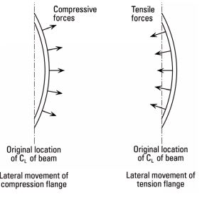
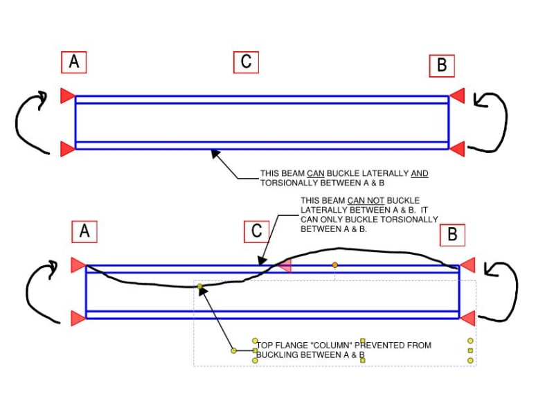
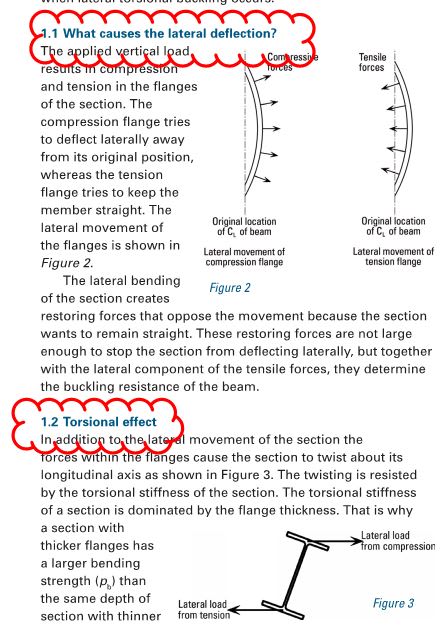
Invariably, somebody chimes in with "I disagree, LTB is really caused by the compression flange acting like a column and trying to buckle laterally while the tension flange attempts to straighten itself out". This is the argument shown below. I defend my position vigorously but, really, I sympathize. Most of the time, I think that compression flange buckling really is the bulk of the LTB story and that LTB can pretty accurately be envisioned as the superposition of two separate effects:

C1) The [L] in LTB. A nearly pure lateral sway about a point of rotation in space above or below the shear center.

C2) The [T] in LTB. A nearly pure torsional roll over about the shear center or a point close to it.

Different situations have different proportions of [L] relative to [T]. For a free cantilever, for example, the center or rotation is somewhere down in the earth's mantle and [L] dominates. In this case, the flange that is furthest from the center of LTB rotation, and would deflect the most, is the most efficient to brace. That flange may or may not be in compression as the free cantilever example demonstrates.

For any beam constrained to buckle about a point of rotation at or between its flanges, however, [T] will tend to dominate. In this case, the story of LTB that is "the compression flange buckles as a column" is pretty near to being the complete truth. As such, in this instance, the best (and really only) way to eliminate this source of instability is to brace that column (compression flange).

c01_afs51q.jpg


c06_mera3l.jpg


D) THE THEORY

AS4100 said:
5.5.2 Segments with both ends restrained. The critical flange at any section of a segment restrained at both ends shall be the compression flange.

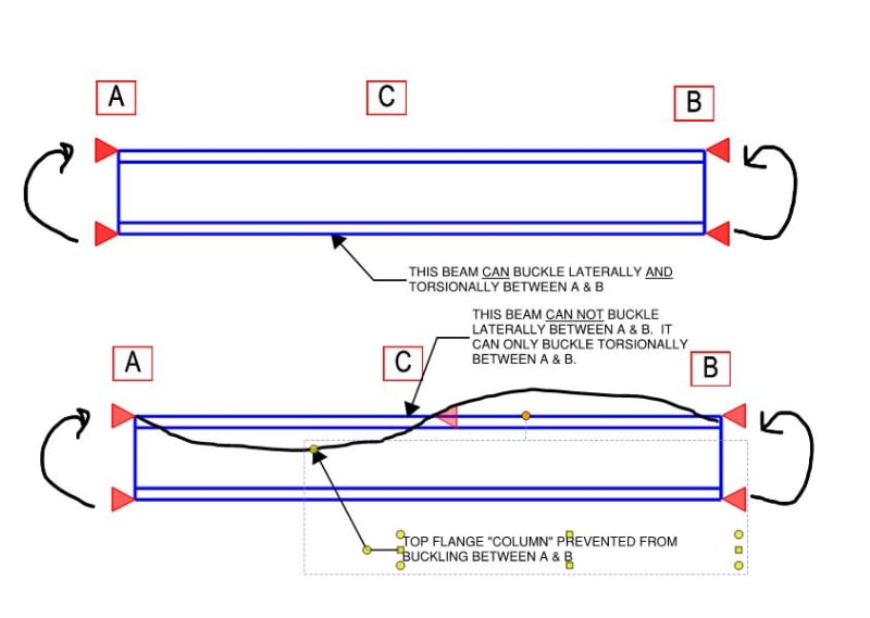
So what's special about an end restrained beam segment that allows it to be put into this convenient bucket where the compression flange is always the critical flange? I contend that the special feature of such a beam is that, once a meaningful, lateral brace is added along its length, it becomes a member in which twist ([T]/C2) dominates and lateral sway ([L]/C1) is effectively off of the table without further designer attention. And this is why braces must prevent lateral movement and not just twist for the AS4100 method (A2). A brace can't be imagined to rule out the lateral component of LTB if it doesn't, you know, restrain the lateral component.

Once the source of instability associated with lateral sway ([L]/C1) has been stripped away by the lateral brace, the only remaining source of instability is that associated with pure-ish twist ([T]/C2). And since that is instigated by something resembling pure "column buckling", the only rational way to deal with that is to laterally brace the compression flange. This is why tension flange bracing is deemed useless when applying this portion of AS4100 (A3). Tension flange bracing would improve twist ([T]/C2) resistance but it wouldn't come close to eliminating it because the compression flange could still "column buckle" and force rotation about the axis of the tension flange.

E) THE CONCLUSION

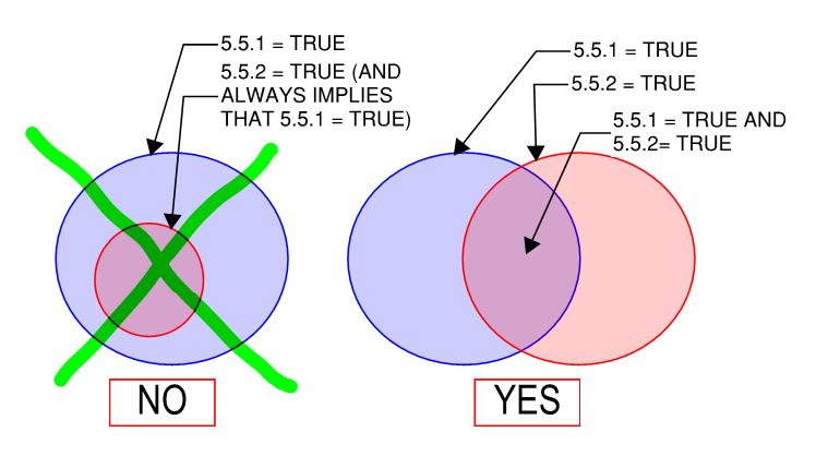
5.5.2 Should be read literally, as the compression flange being the critical no matter what (A1). It isn't actually the case that 5.5.2 is a subset of 5.1.1. They are separate and one need not imply the other as shown below.

c03_kqcf3f.jpg


c05_gepn4x.jpg
 
Human909 said:
Going back to rotational restrains being used for mulitple adjacent beams. It seems that plenty of Australians may be doing it wrong, that includes myself:4.1.5: "Cross-sections that are not effectively prevented from deflecting laterally are treated as unrestrained in AS4100, no matter how effective the restraint against twisting may be", then suggesting that design by lateral buckling can be used if this is considered too conservative.

1) I don't think that rotational only bracing is for real wrong; it's just not consistent with the AS4100 procedure for the reason that I suggested in my All-encompassing Theory post. Presumably, if you use a different method to assess stability, or a buckling analysis as you've suggested, you'd be fine. I think that this may have been what steveh49 was suggesting with his reference to the bridge design world. In that space, situations routinely come up where rotation only bracing is necessary/convenient.

2) From an energy perspective, a beam that doesn't rotate doesn't buckle. A beam can sway laterally until hell freezes over but lateral motion alone doesn't bring the load any closer to the earth and, therefore, doesn't represent buckling instability.

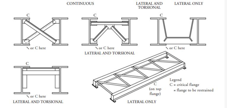
3) For the scenarios shown below, one could make the argument that the thing that we're calling the "beam" is really a single, composite member represented by each pair of members connected together torsionally. In that way, each two member "beam" could be designed in compliance with AS4100 as a torsionally awesome beam having no intermediate bracing. Just sayin'.

c01_qke4c2.jpg
 

Kootk said:
5.5.2 Should be read literally, as the compression flange being the critical no matter what (A1). It isn't actually the case that 5.5.2 is a subset of 5.1.1. They are separate and one need not imply the other as shown below.
Yes we discussed this previously. Most of us seemed to agree that 5.5.2 is separate (though overlapping) with 5.5.1.

In my opinion it's still very murky.

L restraints only laterally restrain the point they're attached to. They don't laterally restrain the entire cross section. As it rolls the entire cross section except the point of support continue to move laterally.
 
Tomfh said:
Yes we discussed this previously. Most of us seemed to agree that 5.5.2 is separate (though overlapping) with 5.5.1.

Yup, but as far a I know, my latest theory is the only rational explanation for "why" so far proposed.

Tomfh said:
L restraints only laterally restrain the point they're attached to. They don't laterally restrain the entire cross section. As it rolls the entire cross section except the point of support continue to move laterally.

I offered a complete explanation for that in my theory, centered around the diagram below.

c06_gvkmun.jpg
 
Kootk said:
I offered a complete explanation for that in my theory, centered around the diagram below.

But what about the bottom flange moving laterally?

I don't draw the distinction between torsion and lateral movement you do. It's a global translation. I don't think it's right to say the beam isn't moving laterally and is merely twisting. When the top flange is pinned and the beam rolls the beam centroid still translates and rotates. Certainly it rotates a lot less than with no lateral restraint, but it's still not pure rotation/torsion.
 
Tomfh said:
I don't draw the distinction between torsion and lateral movement you do.

If you're not willing to entertain thinking in those terms then, truly, my theory is not for you as it's very much predicated upon that. However, as shown below, I am far from the first to think of LTB in terms of largely separated twist and lateral sway components. And I contend that the writers of AS4100 may have been thinking in this way too.

Tomfh said:
But what about the bottom flange moving laterally?

The bottom flange moving laterally only contributes to the instability associated with the lateral sway of the cross section. For the component of instability associated with twist alone, the bottom flange is actually improving the stability of the situation. As such, once the lateral motion is removed from the system by a new brace, so is the instability associated with tension flange lateral movement.

Tomfh said:
Certainly it rotates a lot less than with no lateral restraint, but it's still not pure rotation/torsion.

You'll notice in my work that I took care to always describe it in terms like nearly pure rotation rather than just pure rotation. My supposition is that there's a world of difference between LTB where the center of rotation is in the earths mantle and LTB where the center of rotation is within the depth of the cross section.

KootK said:
C1) The [L] in LTB. A nearly pure lateral sway about a point of rotation in space above or below the shear center.

C2) The [T] in LTB. A nearly pure torsional roll over about the shear center or a point close to it.

KootK said:
For any beam constrained to buckle about a point of rotation at or between its flanges, however, [T] will tend to dominate.

These are all statements that I chose to phrase as I did specifically to acknowledge that the separation between church and state is imperfect.

c01_re9lst.jpg
 
Yes there is such a thing as pure (or nearly pure etc) lateral movement, and yes such a thing as pure torsional movement, and yes AS4100 and Trahair are well aware of that.

What I'm saying is that in reality it's not nearly such a neat distinction in a buckled beam. A lateral brace doesn't eliminate lateral movement and leave (near)pure torsion as you seem to be suggesting. The beam is swinging about the lateral restraint, which involves lateral and torsional motion. A buckled laterally restrained beam doesn't look like your "1.2 Torsional effect" diagram. The beam has moved laterally, as well as twisted. It's simply not a "near pure twist".
 
KootK -> Your theory seems to offer a good explanation of what the code writers may have been implying, but then I'm lead to beleive that we (maybe not we) are interpreting the braced points incorrectly. Going back to the 70' long fixed-end beam problem that you and human909 worked out and found that the buckling load is much lower than the AS4100 would predict... I just can't imagine they would overlook a situation like this. In which case the unbraced length should be interpreted differently. I'm not familiar enough with AS4100 to address this though. Also in the same breath though, I'm reminded of the number of structures that I've seen with continuous beams and no stiffeners/braces at columns and have not had issues (yet?).

EIT
 
Rfreund said:
Going back to the 70' long fixed-end beam problem that you and human909 worked out and found that the buckling load is much lower than the AS4100 would predict... I just can't imagine they would overlook a situation like this.

I think that is the most productive area we should keep looking at.

It would be odd for the code writers to overlook such a major discrepancy, and AS4100 seems to work.

And yet we are showing plausible buckling modes that clash with the spirit of L restraints being as good as F restraints.
I don’t believe we have got to the bottom of how L restraints can be just as effective as F restraints, when we are seeing rotation at the restraint points in the models.

Are we just missing something? Or is AS4100 possibly unconservatively, and works because of additional restraints you get in real structures, e.g. some rotational fixity at "pinned" purlin and joist connections.


RFreund said:
@Kootk regarding your analysis/conclusions in the 23 Nov 19 19:37 post:
You wanted to put to bed the W27x84; 32ft;....
Your conclusions seem to indicate that the AISC LTB check using braced length of 32' would be fairly conservative in this case, correct? You were checking the results that Celt83 originally ran?

I actually only ran that because steveh49 asked for it. That said, that one would be pretty close to the "put it to bed" number. I'd been meaning to do that exercise anyhow so here it is, cleaned up with the full set of braces and no accounting for imperfections.

Mp = 1016 k-ft = AISC plastic = AS4100 plastic

Mn = 589 k-ft = AISC LTB number done the usual way assuming a member with no intermediate restraint.

Mb = 1171 k-ft = AS4100 LTB number assuming a segment length of 8'. This exceeds Mp of course.

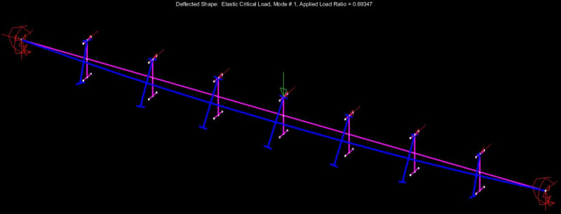
Mastan = 690 k-ft = 250k x L/8 x ALR = 250k x L/8 x 0.69.

So you're getting a 17% bump by going from regular AISC LTB to constrained axis AISC LTB. This actually seems pretty modest considering you're going from no intermediate restraint to, basically, a continuously braced top flange.

Mastan elastic critical buckling, sans imperfections comes in at 50% AS4100 LTB. Shutout to Celt's spreadsheet for running the AS4100 for me. It takes a village.

Mastan file can be found here for review & tinkering: Link

c01_jkpq9f.jpg
 
Kootk, aren't you actually comparing the As4100 capacity to AISC capacity to a elastic critical buckling moment though? They are two different things and not comparable in any way. I've said it a few times now in the thread but if I'm reading it right people don't understand me or something? The mastan2 buckling moment is not the design capacity.

Mastan2 is giving you alpha_m times M_o. You can back calculate out alpha_m using the equation for M_o, or by working out M_o by setting up the alpha_m = 1.0 case in mastan2. (see here if you didn't already look at it when I posted earlier)

Edit, just to clarify for multiple segments you need to follow 5.6.4 procedure, and evaluate on a segment by segment basis still for critical limiting segment

Then work out alpha_s using M_o, then capacity = alpha_m x alpha_s x Msx x phi.

Can you confirm you are doing this please when comparing these numbers?

kootk said:
Mastan elastic critical buckling, sans imperfections
I'll say it again, you don't need imperfections modeled when doing the eigenvalue analysis (elastic critical load analysis in mastan2).

 
kootk said:
For this example, see the plot below and this Mastan file: Link. Quick notes:

- Span = 70 ft = 21.3m
- Sub-segment length = 7 ft = 2.13m (10th points. Probably doesn't matter much as long as it's close enough to force the constrained axis buckling mode.
- Elastic critical analysis.
- No imperfections modeled so a high side estimate.
- Fy inflated to ensure an elastic buckling failure mode.
- No weak axis rotational restraint at the ends.
- Applied Load Ratio = 0.1026
- Fails at 0.1026 x 250k = 26k point load
- Fails at 2768 kip*in end moment = 313 kN*m (25% of your phi.Ms. value of 1240 kNm)

CONCLUSION: if I've not screwed anything up, I believe that this would suggest that the beam length at which constrained axis LTB would occur can be expected to be significantly shorter than the value at which AS4100 would predict that LTB would govern over phi.Ms.

When I check your file to see what everyone is going on about regarding the apparent unconservatism (because I haven't really been following along with tht line of the conversation), I note the model doesn't have warping set to continuous. So results are not quite valid as you get a reasonable benefit from this.

But I am seeing the same differences in capacity, in my checks on the 70 ft case with L restraints only in the 5/8, 4/8, 5/8 span locations as per code requirement for consideration. The end span is critical. The difference from the hand check over 8001mm segment gives ~phiMbx = 682kNm. But the capacity from a buckling analysis method is coming out at phiMbx = 269kNm. This is just using table 5.6.1 case 1 for calculating alpha_m (have not calculated alpha_m using 5.6.4(b) method to see if that would be different).

 
Status
Not open for further replies.

Part and Inventory Search

Sponsor