Continue to Site

Eng-Tips is the largest engineering community on the Internet

Intelligent Work Forums for Engineering Professionals

  • Congratulations KootK on being selected by the Eng-Tips community for having the most helpful posts in the forums last week. Way to Go!

Rafter without fly brace? 22

Status
Not open for further replies.

fourpm

Industrial
Oct 12, 2019
13
I am designing rafters to AS4100 and wondering what if I don't use fly brace. I understand that with fly brace it will give you full restraint. But if I don't use fly brace, will the purlin above be considered as lateral restraint for rafter under uplift? If so. can I take the purlin spacing as segment and the only factor that changes without fly brace is kt?
I have the same question when it comes the continuous steel floor beam design where Z/C floor joints sit on top of the beam. What segment should I take for the beam near the support? Can I take the floor joists spacing as segment with lateral restraint? Can anyone give me some examples? I have read some manuals but the examples they have are simply supported beams only. Thank you.
 
Replies continue below

Recommended for you

Tomfh said:
Question for everyone: Why do the Mastan models predict Kootk's bottom flange buckle, but human's FEM model (and the graphs) predict localised buckling between lateral restraints?
Excellent question.

I hope to look into my model deeper today, but this depends time constraints.... I'll recheck my results and check other buckling modes. There is a good chance that somewhere along the line I'll see the full wave bottom flange buckling. (In many of the cases I have seen this as the first buckling mode. A complete constrained axis buckling does normally result in this. But the model isn't truly fully restrained, it only has restraints every 2.1m)

His results also seem to occur at a MUCH lower load and below AS4100 code so I suspect something is amiss. If anybody could replicate or check Kootk's mastran results that will be great.
 
Tomfh said:
It’s one thing to treat L as the same for design purposes, but really and truly just as good?

To the extent that [as good = as efficient at preventing sectional rotation], the L-brace certainly is not just as good. But, with stability bracing, what really matters is whether or not the bracing is good enough to force a higher mode of buckling.

I stumbled across an interesting case of the weird stuff that can happen when exploring the uplift situation. The combination of a few L-braces, and a load applied in a high stability vertical position. created the effect of a an F-brace at mid-span. There is much that makes this example only weakly analogous but, again, weird stuff happens in the land of stability.

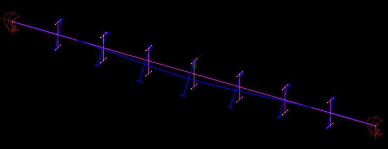
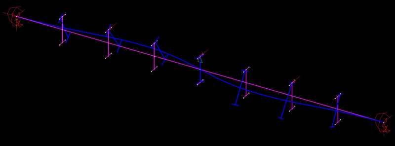
In order, below, you're seeing:

1) No L-brace.

2) L-brace at mid-span only.

3) L-brace at mid-span and each 1/4 point immediately to the side.

My best explanation for this is that, once the top flange L-bracing is effectively continuous, the load being applied in a stabilizing position overpowers the tendency towards a single curvature buckling mode.

c01_q493js.jpg

c02_wqygcn.jpg

c03_jqqz1j.jpg
 
RFreund said:
That's a good point. There are actually some tests out there that show there is some, but that is a different discussion for a different day.

You'll find a good chunk of that information here: Link. It's super old though. Like, inflection point bracing old. I agree though, adding this effect to an already complex discussion wouldn't be likely to help anything.

c01_gg5djm.jpg
 
kootk said:
To the extent that [as good = as efficient at preventing sectional rotation], the L-brace certainly is not just as good. But, with stability bracing, what really matters is whether or not the bracing is good enough to force a higher mode of buckling.

Agree. My confusion is because Agent's graph says an L restraint on critical flange provides identical performance as an F restraint, and that an L restraint on non critical flange is identical to no restraint. The graph refers to simply supported beam, but the same logic applies to our scenario.

Likewise human's buckling examples show the Laterally restrained beam acting as though it's Fully restrainted. It is confining the bottom flange buckles to very short wavelengths, of (approximately) same length as the top flange restraints spacing. That again would suggest L is as good as F. But I can't understand why the beam would bother doing this, as opposed to a gentler wavelength similar to the mastan buckled shapes, and your original paint sketches.
 
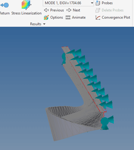
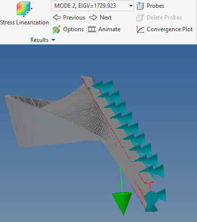
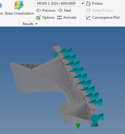
Ok here are some picures of the different modes for Kootk's 70ft beam:
First 3 modes in order including the calculated buckling forces in kN. (You'll notice the first one is about 5% less than I previously reported this is due to me refining the restraint points to a smaller point on the mesh.)
1_sjre8o.png

2_jqzcfg.png

3_mws0a7.png


The bottom mode is essentially Kookt's full wave buckling mode. It comes in much later. Not suprising really because it takes a fair bit more energy to buckle a 21m beam than a 2.1m sub section.
 
Human, Are those restraints pin? The top flange doesn't seem to be rotating, and the web appears to be bending? I could be wrong. It's a bit hard to see...
 
Tomfh said:
But I can't understand why the beam would bother doing this, as opposed to a gentler wavelength similar to the mastan buckled shapes, and your original paint sketches

Yesir. I'll make the identical argument below.

Human909 said:
Full mode buckling doesn't have to be full lenght.

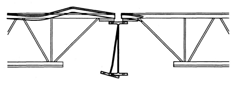
I agree and posted an interesting example of this myself two posts back, complete with a proposed explanation for the unexpected shape. That said, these are complex software algorithms that we're using and stability can get crazy complex at times. When like something strikes me as spurious, I feel compelled to find an explanation for it before moving on. In this case, this is what I find spurious.

1) My software and yours disagree. Obviously they can't both be right. If your software showed my buckling mode, or my software showed your buckling mode, I'd feel a lot more confident.

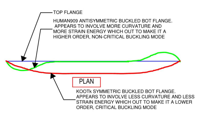
2) As Tom mentioned above, your buckled mode shapes would seem non-optimum from an energy perspective with respect to the shape that the bottom flange takes on. That doesn't necessarily mean that shape is wrong but I would like to find an explanation for it before collectively agreeing that it's right. Are you able to offer any explanation for the double curvature mode shape at this time?

c01_n29czk.jpg
 
Human909 said:
Not suprising really because it takes a fair bit more energy to buckle a 21m beam than a 2.1m sub section.

I believe that it's the reverse actually. The longer unbranded length should require less strain energy to initiate buckling. That's what makes it go first.
 
@Human909 - is your beam fixed at the support against major axis bending and released in the minor axis?
Sorry this might have been asked before, but it looks like there is no major axis restraint.

@Kootk regarding your analysis/conclusions in the 23 Nov 19 19:37 post:
You wanted to put to bed the W27x84; 32ft;....
Your conclusions seem to indicate that the AISC LTB check using braced length of 32' would be fairly conservative in this case, correct? You were checking the results that Celt83 originally ran?


EIT
 
Kootk said:
1) My software and yours disagree. Obviously they can't both be right. If your software showed my buckling mode, or my software showed your buckling mode, I'd feel a lot more confident.
I'm looking at mine carefully. I don't have the confidence to say mine is right over yours.... For simple Euler buckling the results from NASTRAN FEA match up with theory extremely well and it isn't particularly sensitive to mesh size. I've been having a close look at mesh size effect in the last 20 minutes and it still seems sentive to mesh size so I should refine the mesh until it isn't. (Obviously bigger meshes mean significantly longer run times expecially with a 21m beam!

Kootk said:
I believe that it's the reverse actually. The longer unbranded length should require less strain energy to initiate buckling. That's what makes it go first.
I can see both sides of the argument. The shorter length means less beam involved AND only involves on 2.1m segment unlike you drawing which shows two 2.1m segments. It also is occuring where the compression in the bottom flange is the greatest.

BTW refining my mesh is converging on lower values of buckling force ~1000kN. Which would imply that AS4100 is unconservative here. (Which is what Kootk has previously claimed)

Though I'm still seeing single segment buckling as the first buckling mode. Full beam buckling doesn't come into play until ~2.5x the force.
 
Human said:
The shorter length means less beam involved AND only involves on 2.1m segment unlike you drawing which shows two 2.1m segments.

Symmetry means you should have both though. Your two modes show them both happening at almost the same load. Because the meshing will be a bit assymetric, I think the software is splitting it into two modes, when really they are one and the same. Your earlier example shows it doing what kootk has drawn, with both appearing in one mode.


Can you confirm what the top restraints are? See my question 25 Nov 19 01:19. I'm trying to understand why your images appear to show web distortion.
 
Tomfh said:
Symmetry means you should have both though. Your two modes show them both happening at almost the same load. Because the meshing will be a bit assymetric, I think the software is splitting it into two modes, when really they are one and the same. Your earlier example shows it doing what kootk has drawn, with both appearing in one mode.
True.

Tomfh said:
Can you confirm what the top restraints are? See my question 25 Nov 19 01:19. I'm trying to understand why your images appear to show web distortion.
Top restraints are lateral only every at 10% spacing. They are currently area restrains so some rotational restrain might come into play. I can try line restraints and see if there is a significant change.....

Okay.... Thanks for pressing me on this Tom. With single point vertex restraints my model starts to look alot like Kookt's model. And does imply massive unconservatism from AS4100 in this circumstance. In fact I'm now down to 159kN with non linear elastic analysis! (compared to 1154kN member capacity from AS4100) Whether this unconservatism manifests in reality is a good question. The lack of ANY stiffness given at the restraints is not realistic and as we have seen the theoretical buckling analysis is very sensitive to even minor rotational stiffness at points.

-My modelling has used small face restraints that has implicit rotational stiffness even if the restraint is translational only
-These implicit rotational stiffnesses in the restrains have had significant affects from a TRUE point restraint
-With tighter meshing and better use of point restrains I'm seeing similar behaviour too kootk's modelling

Result:
Kootk (1)
Human909 (0)
[rednose]
 
So AS4100 is actually relying on some rotational restraint at L-restraints?, even though the premise of L restraints is no rotational restraint?
 
RFeund said:
So this could be:
FLLLLLLLF
FPP---PPF

No because an L restraint to the top flange tension is an unrestrained section for the bottom flange. The code explicitly states this.

Mastan gives you something above AISC equation because AISC is assuming LTB vs Constrained axis buckling

Mastan is simply solving for the critical buckling mode, whatever that happens to be, it's not really important.

Mastan gives you elastic buckling lower than what AS4100 gives you.

No, it gives exactly the same, in so far as as long as alpha_m estimation is similar the numbers will be the same. An elastic buckling analysis is code agnostic if you like. What you do with the elastic buckling moment is of course where the codes differ, but they differ in the same way that the hand methods differ.
 
Tomfh said:
So AS4100 is actually relying on some rotational restraint at L-restraints?, even though the premise of L restraints is no rotational restraint?
I would suggest not.

If what these models Kootk's and now mine are showing is correct then it is a case of AS4100 just not looking for and therefore not finding the buckling modes in the bottom flange. Which would imply what Kootk has been saying all along is correct. On the other hand if what Kootk is correct and AS4100 completely misses all this then the next question is how does AS4100 get away with this?

One very big unrealistic part of this model is the lack of ANY restraint in the minor axis of the beam but complete restraint in the major axis. You have to try pretty hard to do that.
 
Human said:
then the next question is how does AS4100 get away with this?

If your buckling numbers are correct then yes indeed...

I always assumed that lateral restraints, whilst not actually producing a buckling mode with half wave length X, nonetheless produced a mode that was less critical than a reference case with half wave length X.

If in fact it doesn’t and L restraints can result on a lower buckling load than AS4100 assumes, then I have no idea how L restraints work.

Human said:
One very big unrealistic part of this model is the lack of ANY restraint in the minor axis of the beam but complete restraint in the major axis

Are you talking about lateral rotational restraint? I.e. kr factor? You’re saying that even though we may assume say kt=1.0, that it’s not really 1.0?


Hopefully there is just something wrong with the analyses, or someone’s forgotten to carry the 1 somewhere along the way....
 
Tomfh said:
Are you talking about lateral rotational restraint? I.e. kr factor? You’re saying that even though we may assume say kt=1.0, that it’s not really 1.0
I'm talking about the end restrains of the beam. I've tried to replicate Kootk's model which from what I understand has end restraints that are rotationally fixed in the major bending axis but totally without rotational restraint (pinned) in the minor bending axis.

Tomfh said:
Hopefully there is just something wrong with the analyses, or someone’s forgotten to carry the 1 somewhere along the way....
There have been a few misses with analysis as variations in assumptions make a big deal. But I'm not sure what kookt has presented and I have now come close to replicating is wrong. It is just that you'll struggle to find such perfect pinned lateral restraints and perfectly pinned minor axis restraints. But it does call into question the shortcut that AS4100 is taken which is what kootk has been pushing at for a while.
 
Human said:
I understand has end restraints that are rotationally fixed in the major bending axis but totally without rotational restraint (pinned) in the minor bending axis.

I may be misinterpreting you, but isn’t fixed major axis merely beam continuity (a perfectly feasible scenario), and isn’t the lack of minor axis restraint merely the absence of what the code refers to as lateral rotational restraint?
 
KootK said:
Verifying that this is how AS4100 works

A situation where appeal to authority is the only option. You must be in uncomfortable territory! I've attached a paper by Trahair et al explaining AS4100's lateral buckling method. For those who don't know, Trahair was the co-chairman of the committee that developed AS4100 and was probably 'the guy' on the lateral buckling provisions. Yura might be the US equivalent (?)


Some sections that are relevant to the various directions this discussion is taking are:

- 4.1.4: "Despite this lack of restraint against twist rotation, laterally-restrained intermediate cross-sections... act effectively as if fully restrained." But for just the equivalence of L restraints to F restraints in AS4100 I don't think we need this article. You would only need to look at one page of the code I think - the tables for the factors that contribute to effective length L_e. Anywhere there's an option for L restraint, substitute F restraint and the factor is the same. FF = FL = LL and FP = PL. (Except k_r as noted before.)

- 4.1.5: "Cross-sections that are not effectively prevented from deflecting laterally are treated as unrestrained in AS4100, no matter how effective the restraint against twisting may be", then suggesting that design by lateral buckling can be used if this is considered too conservative.

- 4.3.3: Load height factor at point of lateral restraint. See the 5th paragraph. This seems to imply that a bottom non-critical flange won't move sideways at all when the top flange is L-restrained. Perhaps the case without moment reversal, see below.

KootK said:
Justifying that this approach is theoretically appropriate.

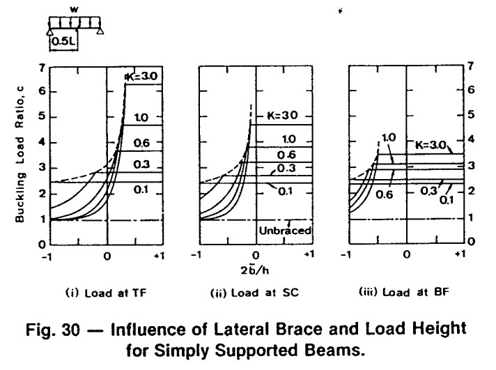
I haven't done an exhaustive literature review and am not capable of doing so, but when I do read about LTB it seems that simply-supported beams without moment reversal are very commonly the case that is considered unless moment distribution is specifically being investigated. Then the simply-supported case is assumed to apply generally without any rigorous proof. Since first coming to this topic, I have wondered if that is the case with L restraints. That graph I posted that shows critical flange L restraint exactly equalling F restraint (like in AS4100) and non-critical flange L restraint doing exactly nothing (like in AS4100) was for the simply supported case - no moment reversal. The paper it comes from only covers simply-supported and cantilever beams: top flange always critical. The paper is Australian, from 1986 (a few years before AS4100 was first published in 1990) and you can see how the AS4100 rules would be a conservative simplification for the cases covered. My suspicion is firming that the AS4100 L-restraint rules were written without any consideration of moment reversal.

Tomfh said:
I’m not sure how an L can really be as good as F in reality, or how L on non critical flange can do literally nothing...

It's complicated. Here's a fuller picture. Note for beams where St Venant torsion dominates over warping torsion (K=0.1), the restraint location on the cross section doesn't matter at all. 2*b_bar/h = -1 is the bottom flange (b_bar is the brace distance above the shear centre/centroid).

L_bracing_higwn5.gif
 
Status
Not open for further replies.

Part and Inventory Search

Sponsor