Continue to Site

Eng-Tips is the largest engineering community on the Internet

Intelligent Work Forums for Engineering Professionals

  • Congratulations KootK on being selected by the Eng-Tips community for having the most helpful posts in the forums last week. Way to Go!

Rafter without fly brace? 22

Status
Not open for further replies.

fourpm

Industrial
Oct 12, 2019
13
I am designing rafters to AS4100 and wondering what if I don't use fly brace. I understand that with fly brace it will give you full restraint. But if I don't use fly brace, will the purlin above be considered as lateral restraint for rafter under uplift? If so. can I take the purlin spacing as segment and the only factor that changes without fly brace is kt?
I have the same question when it comes the continuous steel floor beam design where Z/C floor joints sit on top of the beam. What segment should I take for the beam near the support? Can I take the floor joists spacing as segment with lateral restraint? Can anyone give me some examples? I have read some manuals but the examples they have are simply supported beams only. Thank you.
 
Replies continue below

Recommended for you

Agent666 said:
If I do a buckling analysis for a scenario like this, I get the top compression flange buckling the furthest at midspan where you proposed the L restraint. So I'm just never seeing this effect you are noting at that mid point of the middle span that the tension flange is buckling the furthest like you're stating/proposing?

Back to this with Mastan using this file and the methodology described below: Link

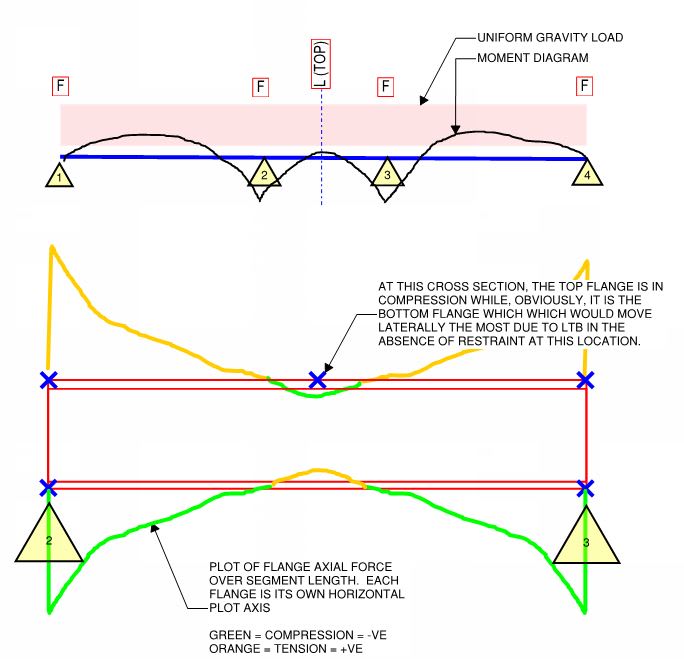
Doing it this way, I was able to create a situation in which the following is true at the mid-span section where one might contemplate a brace;

1) The bottom flange is in tension.
2) The top flange is is in compression.
3) The bottom/tension flange would move the most (+1.00 for the bottom/tension flange; -0.68 for the top/compression flange).
4) One might rationally expect that the bottom/tension flange would be the best place for this brace.

And yes, this was very much a contrived example designed to produce this effect. As such, the example's practical significance is limited.

KootK said:
My intent was to propose something almost like a calculus/limits scenario whereby the zone of compression in the top flange would effectively shrink to zero. Or, say, 6". In such a scenario, you'd have virtually all of the top flange in tension and virtually all of the bottom flange in compression. I had thought, with great confidence, that this would produce a situation in which:

1) The compression/critical flange for the first, central L-restraint would be the top flange but;

2) At the location of the central brace, it would be the bottom flange that moved the most.

But, then, your FEM says otherwise. I may have to fact check that with my own FEM, however, as I'm not sure that you modeled thing as I would have. Changes I would make include:

4) I'd shrink the zone of top flange compression a great deal.

5) I'd model the central span on it's own without weak axis end fixity.

If that still doesn't show the results that I expect, I'll just a have to accept that my instincts on this one led me astray. It won't be the first time.

c03_vdaupv.jpg


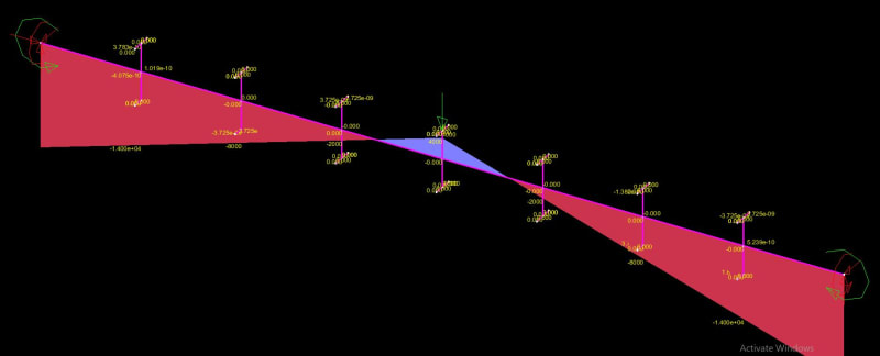
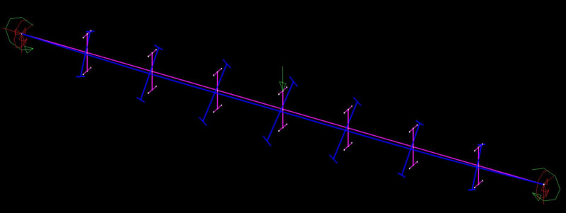
c01_lgatuy.jpg


c02_mpdgme.jpg
 
I'm hoping someone will take mercy on me as this is a long thread and I'm having a hard time establishing what the argument is. A couple questions might help those who later find this:

Can you define and L-brace and a P-brace?

My understanding of the argument:
If you have a continuous beam or in the example above a fixed end beam, what is the unbraced length for buckling assuming:
[ul]
[li]The top flange is restrained against lateral translation[/li]
[li]At the ends of the beam the Top flange is restrained against lateral translation and the bottom flange cannot rotate/translate relative to the top flange.[/li]
[/ul]

It seems like everyone has agreed that it should be defined as the length between "columns"
Then it seems we discovered there is some benefit to having the top of the beam braced against lateral translation even when checking the end (negative) moments. This benefit is or is not codified?

I'm I close?


EIT
 
Tomfh said:
Ok good. Then you understand why AS4100 considers it ineffective. Not sure why you needed to fight over it

Firstly, I don't "fight". I debate like a civilized person. If you see this as fighting, that says more about your mindset than mine.

Secondly, I continued to debate this because:

1) You neglected to offer any theoretical explanation for your statements and;

2) I wasn't really wrong (34% improvement). Rather, I just wasn't as right as I'd suspected.

I came at this today by:

a) Doing all the research legwork myself.

b) Sharing my research results with others rather than just laying down unsubstantiated claims.

c) Making a point of reporting back to the group that things did not work out as well as I had anticipated.

I consider this to be a gentlemanly and adequate response on my part. To the extent that a mea nulpa was warranted, it's been issued. What more would you ask of me?

If we're "fighting", it's because you couldn't resist diving back in to poke the bear a little more, even though there was really no reason to do so. Frankly, this particular bear doesn't mind all that much so poke away. Just don't lose your composure when I continue to poke back.
 
kootk said:
If we're "fighting", it's because you couldn't resist diving back in to poke the bear a little more

I’m going to respond if you dispute key concepts like the ineffectiveness of lateral braces on non critical flanges.

You started out in this thread saying it is fundamentally wrong to count lateral braces at critical flanges (leading a few people astray in the process), and now here we are and you’re arguing we should be counting not only lateral braces of critical flanges, but lateral braces of non critical flanges.
 
L-Brace said:
Can you define and L-brace and a P-brace?

L-brace: Aussie for just straight up lateral (L) support without providing any torsional restraint to the beam. Usually this is how own would conservatively treat a steel joist tying in.

P-brace: Aussie for a full fixity brace (lateral + torsion) that only does a partial (P) job of being a full fixity brace. An example would be a top side purlin moment connected to the beam supported to it without a stiffener pair on the beam. In reality, all open webbed steel joist connections are somewhat a version of this.

RFreund said:
It seems like everyone has agreed that it should be defined as the length between "columns"

Oh no, not at all. Me, Yura (read that attached paper), and most AISC practitioners see it that way. The Aussie code seems not to and treats the effective buckling length as the length between L-braces. This was the initial source of contention. At this point, we've established that the AISC and AS4100 methods are practiced quite differently. My current bones of contention are these:

1) I don't understand the underlying theory that justifies AS4100 treating the unbraced LTB length as something much shorter than it obviously is in the real world (distance between points of twist restraint) and;

2) The AS4100 method seems to operate on a single, unrestrained LTB buckling mode rather tackling the multiple, possible modes in a hierarchical fashion as we do with AISC. Again, this is a theoretcial understanding issue for me. I just don't undertand how AS4100 works the magic that it seems to. I want a look at the wizard behind the curtain.

RFreund said:
Then it seems we discovered there is some benefit to having the top of the beam braced against lateral translation even when checking the end (negative) moments. This benefit is or is not codified?

I wouldn't say that it was discovered here. I've been mentioning the constrained axis buckling check since the very beginning and extolling its virtues in improving capacity. This is the effect that you've described. As for codification:

1) The base method in the AISC SCM does not account for this.

2) The are AISC documents, such as the Seismic Design Manual, that do provide guidance for constrained axis LTB checking.

3) Frankly, it's hard to say if AS4100 explicitly checks constrained axis buckling or not as nobody seems to really be able to explain how AS4100 actually works. Certainly, the outcomes are much closer to #2 above than they are to #1. And that makes me suspect that, one way or another, AS4100 is dealing with constrained axis buckling.
 
Rfreund said:
Then it seems we discovered there is some benefit to having the top of the beam braced against lateral translation even when checking the end (negative) moments. This benefit is or is not codified?

I'm I close?

Laterally bracing a beam (anywhere) provides some benefit. Some places are especially good to brace. Some are average. Some are very poor. The codes critical flange provisions - in particular the rule to treat the compression flange as the critical flange - are an attempt to formulate this into simple rules.

If you use the simple AS4100 rule (compression flange is critical) you cannot count top restraints in the negative bending moment zone in the way you could under AS1250. You can use a buckling analysis to show the top flange is genuinely critical, but you leave yourself open to criticism because people are squeamish about bracing the tension flange.
 
Tomfh said:
You started out in this thread saying it is fundamentally wrong to count lateral braces at critical flanges (leading a few people astray in the process)

Nope. I suggested that it was incorrect to consider the unbraced LTB buckling length as anything other than the distance between points of twist restraint. And can you really blame me given that:

1) That's what Yura says,
2) That's how AISC, my home code, is applied,
3) That fits the theory that underlies AISC,
4) Nobody seems to be able to explain, theoretically, how AS4100 gets away with doing it differently.

And even if I'm 100% wrong about every damn thing that I've said and done here, so what? I don't just come here to teach others and have my ego stroked; I come here to learn when the occasion presents its self. As such, I'm allowed to be wrong. I'm even allowed to be wrong and then continue speaking after having been wrong. I know, it's craaazy right?

This thread has clearly created a great deal of value for a number of people, me included. Do you really think that would have been the case if I hadn't poked my head in, asked a few questions, and challenged some things? At the end of the day, debate is really the domain of those who actually like to debate. Other folks should consider golf.

c01_yzo38i.jpg
 
Kootk said:
Frankly, it's hard to say if AS4100 explicitly checks constrained axis buckling

It doesn’t check it explicitly. AS4100 capacity equations are an envelope and provided you laterally brace according to the codes “critical flange” rules then you keep your actual
buckling modes within the calculated envelope. AS4100 is just a curve drawn outside all the points. You don’t actually check the points directly.
 
Tomfh said:
It doesn’t check it explicitly. AS4100 capacity equations are an envelope and provided you laterally brace according to the codes “critical flange” rules then you keep your actual buckling modes within the calculated envelope. AS4100 is just a curve drawn outside all the points. You don’t actually check the points directly.

1) Yeah, I've been starting to wonder if that's how it works. That is your understanding, Human909's understanding, but not steveh49's understanding. I'm not sure where Agent666 stands on this.

2) What I'm most interested in now is understanding the basis for, or development of, that envelope of which you speak. I consider such an envelope, that would consider all possible buckling modes, to be an impressive achievement. We in North America should adopt this technology. And so I'd like to understand how it has been developed.

3) Above, you described this envelope as a calculated envelope. I take it that your understanding is that this envelope was arrived at through running computational trials rather than, say, testing or experience?

4) Do you know of anything in print, anywhere, that mentions this envelope? I've not stumbled across a single thing. Given the importance of the envelope, I'd have expected it to be described, at least in passing, in a commentary, textbook, or something like that. How did you come to know of its existence?

5) The 70' case that I ran for steveh49 suggested that the AS4100 provisions did a poor, and very unconservative job of estimating the beam length at which LTB would begin to govern. Perhaps that example is so extreme as to be outside the realm of practical application.

6) Even if AS4100 is partly empirical, it cannot be entirely empirical. Many of the equations are the usual looking suspects that are consistent with stability theory. At best, it must be an empirical curve indexed to theoretical work, similar to how punching shear is related to the Timoshenko derivation but not exactly that (goal posts moved to suit test results).

 
Kootm said:
2) What I'm most interested in now is understanding the basis for, or development of, that envelope of which you speak.

I don’t know the details, but it is certainly based on theory and experiment.


Kootk said:
he 70' case that I ran for steveh49 suggested that the AS4100 provisions did a poor, and very unconservative job of estimating the beam length

Sorry, are you saying you have found an example where AS4100 is unconservatice and overstates actual beam capacity?
 
kootk said:
Do you know of anything in print, anywhere, that mentions this envelope? I've not stumbled across a single thing. Given the importance of the envelope, I'd have expected it to be described, at least in passing, in a commentary, textbook, or something like that. How did you come to know of its existence?

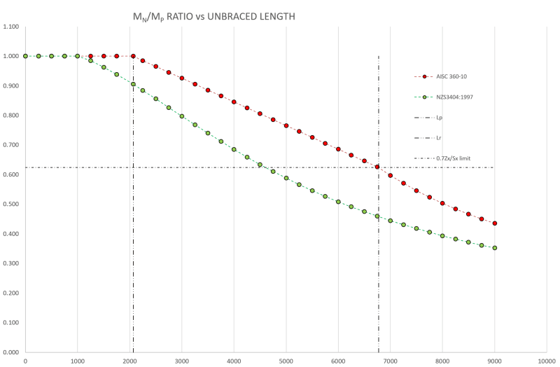
This is what the alpha_s factor does. I've mentioned previously on two occasions now in this thread that I can remember that it savagely scales back the theoretical capacity until every test (159 I believe) which they compared results to was above the line. Whereas AISC goes somewhere through the middle of the test data, and isn't a lower bound approach, more of an average. This can easily be seen in the graph I posted a few posts back. NZS3404 capacity is way lower than AISC for example. I posted a specific comparison much earlier in the thread without all the other cases included. Edit: this was the 'The YELLOW section' graph posted right at the beginning that you commented on.

I'll dig out the references to this aspect. The alpha_s was a curve fitting exercise basically, empirically derived. To match the theory results to what was observed in real world tests.
 
Tomfh said:
Sorry, are you saying you have found an example where AS4100 is unconservatice and overstates actual beam capacity?

Sort of, if one has faith in:

1) steveh49's calculations and;

2) my Mastan modelling and;

3) the validity of a 70' beam example.

Do a "find" in your browser for this phrase: "SURPRISE OBSERVATION". That will take you to the latest post on that. Alternately, it was the second thing that I posted today.

Summary:

1) Running my W27x84 test case through AS4100 indicated that my constrained axis LTB mode was highly improbable.

2) To emphasize #1, Steve calculated the length of beam that would be needed for my test case before LTB would govern per AS4100. This ended up being 65'+ compared to the original length of 32'.

3) I set up a Mastan model that suggested that, at Steve's calculated beam length, you'd be at 400% of the available LTB capacity rather than 100% of the LTB capacity per AS4100.

This is no great smoking gun but it is a discrepancy.


Ok, so Steve is saying that according to AS4100 it buckling as it hits section capacity, and you’re saying it buckling at only 25% of section capacity?
 
Agent666 said:
This is what the alpha_s factor does. I've mentioned previously on two occasions now in this thread that I can remember that it savagely scales back the theoretical capacity until every test (159 I believe) which they compared results to was above the line. Whereas AISC goes somewhere through the middle of the test data, and isn't a lower bound approach, more of an average. This can easily be seen in the graph I posted a few posts back. NZS3404 capacity is way lower than AISC for example. I posted a specific comparison much earlier in the thread without all the other cases included. Edit: this was the 'The YELLOW section' graph posted right at the beginning that you commented on.

I've reviewed and considered the graphs that you posted repeatedly. In doing so, however, they appeared to me to be:

1) Graphs comparing single buckling modes over a range of unbraced lengths and not;

2) Graphs comparing envelopes of multiple buckling modes over a range of unbraced lengths per Tomfh's explanation.

If the graphs are #2, then that's great to know. I don't see how I could have been expected to know that, however, unless someone mentioned it. The shape of these graphs look like every other buckling curve fit that I've seen that were all in reference to a single buckling mode rather than envelopes of several buckling modes.

Agent666 said:
The Adina FEM results were provided by the The Adina FEM results were provided by the author for comparisonfor comparison

If there was an author, does that mean that the graphs are part of a document that you could either share with me or refer me to so that I might review it myself?

@Agent666: as long as I have your attention, can you confirm that your understanding of how AS4100 LTB works matches Tomfh's and Human909's, repeated below? The salient features there being that:

1) The AS4100 procedure checks no particular LTB buckling mode and, rather;

2) Checks all buckling modes at once by ensuring that parameters lie within a set of enveloping curves that encompass numerous intividual LTB buckling modes.?

Agent666 said:
It doesn’t check it explicitly. AS4100 capacity equations are an envelope and provided you laterally brace according to the codes “critical flange” rules then you keep your actual buckling modes within the calculated envelope. AS4100 is just a curve drawn outside all the points. You don’t actually check the points directly.

Human909 said:
As above you seem fixated on the notion that a codified buckling check needs to focus on ONE buckling mode. That is a bit useless really. You need a check (or many checks) that covers ALL buckling modes.

c01_eadgdg.png
 
Tomfh said:
Ok, so Steve is saying that according to AS4100 it buckling as it hits section capacity, and you’re saying it buckling at only 25% of section capacity?

Exactly right in so much as we trust Mastan to work that out and me to use Mastan properly.
 
Kookt said:
- Fails at 2768 kip*in end moment = 313 kN*m (25% of your phi.Ms. value of 1240 kNm)

CONCLUSION: if I've not screwed anything up, I believe that this would suggest that the beam length at which constrained axis LTB would occur can be expected to be significantly shorter than the value at which AS4100 would predict that LTB would govern over phi.Ms.

SURPRISE OBSERVATION: the moments at the ends are different from the moments in the middle. I should have anticipated this, in retrospect, but did not.
I am getting the first positive buckling mode failure at 2844kN. Well past the beams capacity.
temp_zrvnod.png


And for good measure 410kN according to AS4100

Space Gass said:
AS4100 1998 CALCULATIONS FOR GROUP 1 (*=Failure)
------------------------------------

Critical load case is 1, out of 1

Section: W27x84 (I or H section, Rolled/SR)

Failure Crit Start Finish Axial Major Minor Major Minor Load
Mode Case Pos'n Pos'n Force Shear Shear Moment Moment Factor

Section 1 0.000 0.00 0.00 215.00 -1144.88 0.00 1.08
Member 1 0.000 6.390 0.00 -1144.88 0.00 1.01
Shear 1 0.000 0.00 0.00 215.00 -1144.88 0.00 1.35
(1.00)

Grade= 50 Fy = 344.7 MPa
Fyw = 344.7 MPa Fu = 448.2 MPa
Ltot = 21.300 m Lseg = 6.390 m (FL Bot-Top)
kt = 1.00 (5.6.3) kl = 1.00 (5.6.3)
kr = 1.00 (5.6.3) Le = 6.390 m (Bending) (5.6.3)
Lx = 21.300 m (Compression) Ly = 21.300 m (Compression)
Lz = 21.300 m (Torsion)
Ly/ry= 404.8 (Compression) Le/ry= 121.4 (Bending)

Arf = 0.0 mm^2 Arw = 0.0 mm^2
An = 15935.5 mm^2 Ae = 0.0 mm^2 (6.2.2)
Kf = 0.00 (6.2.2) Kt = 1.00 (7.3)
αm = 2.09 (5.6.1.1) αs = 0.44 (5.6.1.1)
αcx = 0.00 (6.3.3) αcy = 0.00 (6.3.3)
αb = 0.00 (6.3.3) βme = 0.20 (8.4.4.1)
βmx = 0.50 (8.4.2.2) βmy = 0.00 (8.4.2.2)
γ = 0.00 (8.3.4) ϕ = 0.90 (3.4)

N* = 0.00 kN
Vx* = 0.00 kN (not considered) Vy* = 215.00 kN
Mx* = -1144.88 kNm (Compact) My* = 0.00 kNm (Compact)

ϕNt = 0.00 kN (7.2) ϕNs = 0.00 kN (6.2)
ϕNcx = 0.00 kN (6.3.3) ϕNcy = 0.00 kN (6.3.3)
ϕNoz = 0.00 kN (8.4.4.1) ϕMo = 750.41 kNm (5.6.1)
ϕVvm = 1057.10 kN (5.12) ϕMf = 847.98 kNm (5.12.2)
ϕMsx = 1240.57 kNm (5.2) ϕMsy = 161.68 kNm (5.2)
ϕMbx = 1154.45 kNm (5.6) ϕMox = 0.00 kNm (8.4.4)
ϕMrx = 0.00 kNm (8.3.2) ϕMry = 0.00 kNm (8.3.3)
ϕMix = 0.00 kNm (8.4.2.2) ϕMiy = 0.00 kNm (8.4.2.2)
ϕMtx = 0.00 kNm (8.4.5.2) ϕMcx = 0.00 kNm (8.4.5.1)

Mx*
---- = 0.99 < 1.00 (Pass) Flexural-torsional buckling (5.6)
ϕMbx
 
Human909, what are your end restraints? Are they restrained against minor axis bending? I think others are releasing this. And are both ends restrained longitudunally, so pinned-pinned rather than pinned-roller?

Buckling length looks like ~30% of total length as used by AS4100. Is that the case?
 
What are you and kootk doing different in your buckling analyses?

 
Human909 said:
Well past the beams capacity.

Can you elaborate upon the point that you intended to make with that statement? For as long as we're discusding elastic buckling capacity, other failure modes are not germane to the discussion. They'll govern over elastic stability... or they won't. Either way, they'll be checks separate, and uncoupled, from LTB.
 
Kootk, he’s saying the beam is yielding well
before it buckles.
 
Status
Not open for further replies.

Part and Inventory Search

Sponsor