Continue to Site

Eng-Tips is the largest engineering community on the Internet

Intelligent Work Forums for Engineering Professionals

  • Congratulations KootK on being selected by the Eng-Tips community for having the most helpful posts in the forums last week. Way to Go!

Rafter without fly brace? 22

Status
Not open for further replies.

fourpm

Industrial
Oct 12, 2019
13
I am designing rafters to AS4100 and wondering what if I don't use fly brace. I understand that with fly brace it will give you full restraint. But if I don't use fly brace, will the purlin above be considered as lateral restraint for rafter under uplift? If so. can I take the purlin spacing as segment and the only factor that changes without fly brace is kt?
I have the same question when it comes the continuous steel floor beam design where Z/C floor joints sit on top of the beam. What segment should I take for the beam near the support? Can I take the floor joists spacing as segment with lateral restraint? Can anyone give me some examples? I have read some manuals but the examples they have are simply supported beams only. Thank you.
 
Replies continue below

Recommended for you

Celt83 said:
so by a literal interpretation of the definition of Lb the unbraced length could be taken as 12'.

One could find gobs of example problems done to AISC practice with a modicum of digging. And, as you know, you wont find a single one that interprets Lb as you have above. So, in terms of the dogma of how how things are interpreted in AISC markets, I don't feel that's in debate.

I certainly agree that we could add more capacity to our negative moment LTB checks by accounting for the constrained axis buckling effect. However, to stay in keeping with the existing AISC LTB theoretical framework, I think that would have to be in keeping with Yura's definition: the distance between points of beam torsional restraint. And it's important to recognize that we already have something for this. An "in the margins" procedure for checking constrained axis buckling exists. It's just not common practice to use us for routine design.

Yura's take on it is repeated below. I'll be waiting with baited breath to hear what AISC has to say about this but I'll also be utterly astonished if they break with Yura on this. It may we Yura providing the answer to your question, either directly or indirectly.

As a side anecdote, I actually started my career with an industry association similar to AISC. I thought that such an experience would be utterly amazing as far a tech development was concerned. I would be at the nexus of developing knowledge surrounded by the best minds in the game! It was one of the most disappointing experiences of my life and I was done with that in a year. The process of answering tech questions at the associations is like this:

1) Question lands on the desk or either an EIT or a PhD that's spent the last decade thinking about nothing other than compound buckling in unequal leg, FRP angles.

2) Question gets forwarded to some committee formed for the purpose. The committee will consist of more PhD's who specialize is something unrelated and some practitioners who probably aren't much more well versed in the issue than the person asking the question. Maybe less. And none of these busy folks really have time for this crap.

3) A shabby consensus is formed from the opinions of the three out of twenty committee members who bothered to respond. And that gets forwarded to the question asker, back through the guy at step #1.

So I don't have a ton of faith in the help desks to help with the truly deep questions. We've had quite a few issues arise here where we've attempted that with mixed results. Answers, even from Larry Muir, to the tune of:

4) The guy who wrote that clause died in 1965 and nobody really remembers how it was derived.

5) AISC considers this an area where designers are expected to apply their own engineering judgment.

c01_rnoxzx.jpg
 
kootk said:
What I find particularly interesting about 5.5.1.1 is th

Kootk, yes that’s another reason why it’s easier to just use the compression flange check.

But for our discussion here you could focus on one single midspan lateral top restraint, which covers the fundamental question at hand, and which avoids those other complexities about adding more and more restraints.
 
KootK said:
Kootk, yes that’s another reason why it’s easier to just use the compression flange check
.

It is definitely easier. But is it more correct? If the compression flange definition and the max movement definition ever find themselves in conflict, it is my opinion that it is the compression flange definition that should take a back seat. Or, better yet, get out of the car altogether.

In support of this, consider that:

1) The max movement definition should be applicable everywhere.

2) The compression flange definition flops at cantilevers.

Usually that which is more generally applicable winds up being more theoretically correct. Back to Einstein again.

Tomfh said:
But for our discussion here you could focus on one single midspan lateral top restraint, which covers the fundamental question at hand, and which avoids those other complexities about adding more and more restraints.

That actually gets back to an issue that I'm going to revisit with Agent666 in my next post. That said, I really don't want to avoid the complexities. In my mind that is fitting the problem to match the desired solution. I seek a general purpose, applies all the time, kind of understanding.
 
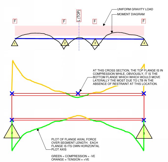
Just some housekeeping on some old questions that I've not yet tended to. It's all in references to the sketches below and the posts that contained the. At long last, I think that I'm up to date on my correspondence.

Agent666 said:
I see what you did, it's a blowup of the middle span! Looking comprehension....

Yeah, I wanted to kick myself in the face as soon as I read your comment. I didn't know how to do the dashed box, blowup thing quickly in blue beam so I figured "it's obviously, nobody will get confused". Obviously not obvious.

Agent666. said:
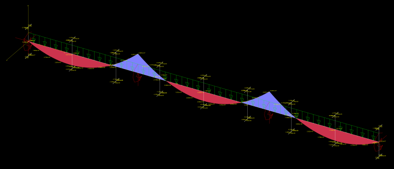
If I do a buckling analysis for a scenario like this, I get the top compression flange buckling the furthest at midspan where you proposed the L restraint. So I'm just never seeing this effect you are noting at that mid point of the middle span that the tension flange is buckling the furthest like you're stating/proposing?

My intent was to propose something almost like a calculus/limits scenario whereby the zone of compression in the top flange would effectively shrink to zero. Or, say, 6". In such a scenario, you'd have virtually all of the top flange in tension and virtually all of the bottom flange in compression. I had thought, with great confidence, that this would produce a situation in which:

1) The compression/critical flange for the first, central L-restraint would be the top flange but;

2) At the location of the central brace, it would be the bottom flange that moved the most.

But, then, your FEM says otherwise. I may have to fact check that with my own FEM, however, as I'm not sure that you modeled thing as I would have. Changes I would make include:

4) I'd shrink the zone of top flange compression a great deal.

5) I'd model the central span on it's own without weak axis end fixity.

If that still doesn't show the results that I expect, I'll just a have to accept that my instincts on this one led me astray. It won't be the first time.

Agent666 said:
But I am seeing in the negative moment region that the top flange in tension is moving further than the compression flange, which I assume is the point you're getting at?

Nope. That is interesting and meaningful but I did not anticipate that and was not looking for it.

c01_m22jy8.jpg


c02_t8jjtt.png
 
KootK said:
One could find gobs of example problems done to AISC practice with a modicum of digging. And, as you know, you wont find a single one that interprets Lb as you have above. So, in terms of the dogma of how how things are interpreted in AISC markets, I don't feel that's in debate.

yeah like I said need to do more reading/re-learning on my end spent a bit to long in the land of concrete, I thought the most appropriate example to find would be a moment frame beam but even AISC's official examples included bottom flange bracing. Got a copy of the Yura paper so plan to digest.

To borrow a term from Agent666's blog, I've been a bit of Sheep on this topic.

Open Source Structural Applications:
 
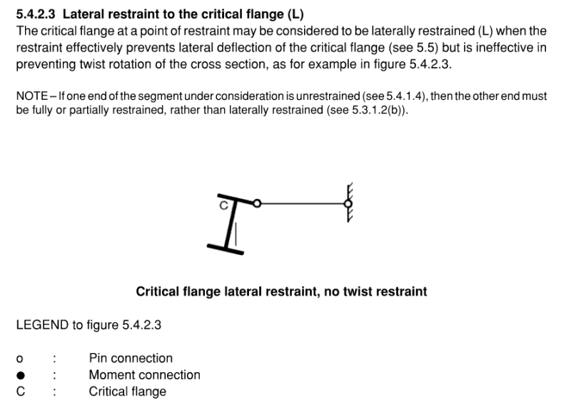
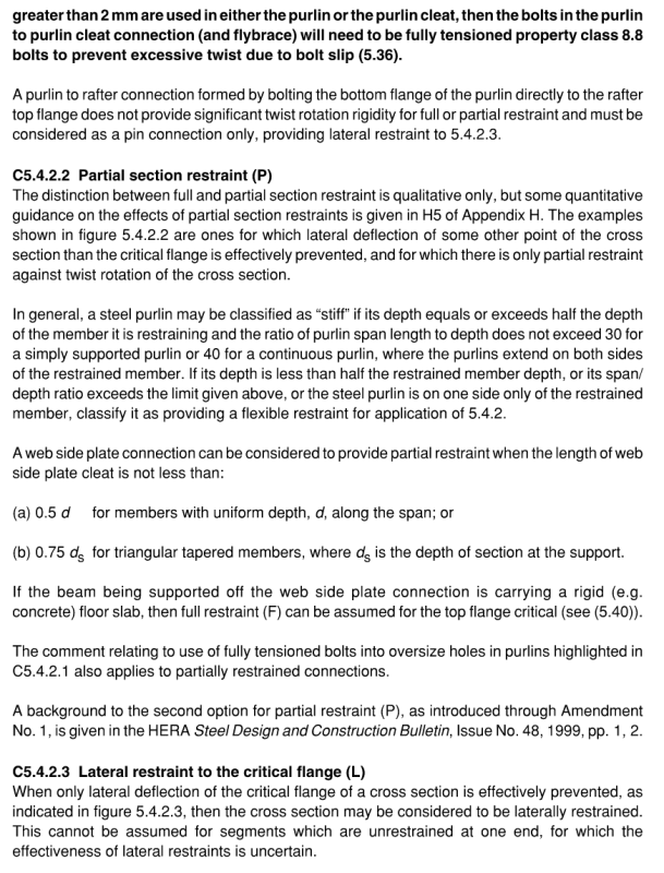
Celt, check out CL 5.4.2.4 (in AS4100) or CL5.4.2.3 (in NZS3404) for the definition of a lateral L restraint. Basically it's pinned to the flange, preventing lateral deflection, but not preventing twist, if attached to the non-critical flange then its considered to do nothing.
Capture_zsyj34.png

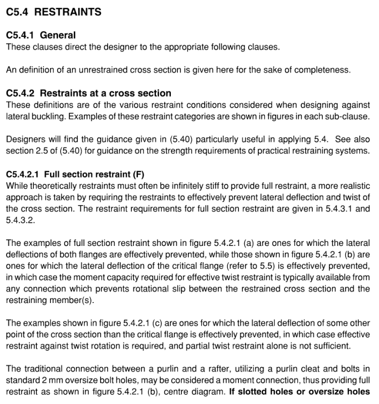
In NZS3404 commentary (unsure if its in AS4100 commentary as well), there are some conditions to meet regarding classifying restraints and the moment/pinned fixity. For a beam or purlin, if of sufficient depth with an appropriate connection, then most certainly it may be able to meet the P restraint condition you highlighted.

Beta_m in NZS3404 is defined as:-
Capture_gogsec.png

I believe this is the correct interpretation, because you'll get quite a different answer if you used the eqn for alpha_m for comparison than what your calculation was in taking it negative.

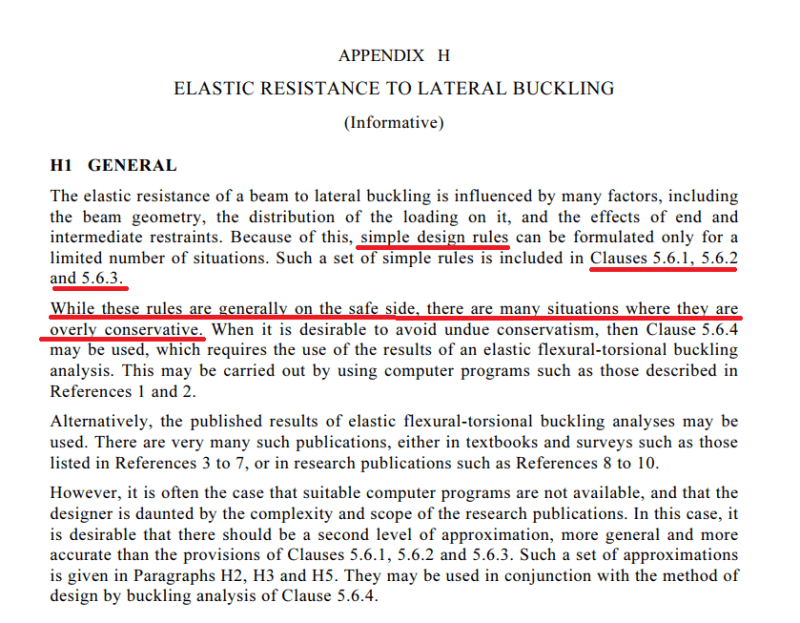
I'll need to read over the AISC guidance, that compression flange criteria you've noted essentially seems like the same thing AU/NZ standards are considering to be honest, even if most people may not have picked up on it.
 
Since I checked and AS4100 does not have the same clarifying provisions, here is the NZS3404 provisions for classification of a restraint:-

Capture_kk203t.png

Capture1_tzcjvi.png
 
Agent666 said:
I'll need to read over the AISC guidance, that compression flange criteria you've noted essentially seems like the same thing AU/NZ standards are considering to be honest, even if most people may not have picked up on it.

It isn't that nobody picked up on it. Rather, it's that we're immersed in examples, software routines, textbooks, and the advice of mentors that all point in the direction of a particular interpretation. Sound familiar?

This is basically the inverse of what I've been up against here with AS4100. Imagine my consternation coming to AS41000, reading nearly identical statements, and finding that they're applied very differently.

The one thing that AISC has going for is that it's very easy to track down the theoretical underpinnings of their LTB method and establish which interpretation is consistent with this. This is just a feature of big market. Derivations for Canadian stuff is often frustratingly hard to track down too.
 
Celt83 said:
yeah like I said need to do more reading/re-learning on my end..

Start with the Yura paper. And, if you want more, I highly recommend the book below. They derive much of the AISC stuff from first principles and show in enough intermediate steps on the math that you should have a pretty good shot at following along.

Celt83 said:
To borrow a term from Agent666's blog, I've been a bit of Sheep on this topic.

Meh... sometimes you're a sheep, sometimes a shepherd. There's too much out there to know for any individual to know it all. I do like the EngVsSheep business. It's perfect for the application sticks in the imagination. If Agent gets hit by a truck, I hope to steel it for my own web presence.

Celt83 said:
Check out Appendix A in TR14 from the American Wood Council

As an aside, I'm pretty sure that recent editions of the Breyer tome on NDS wood design still suggests inflection point bracing for glulam beams.

c01_fnalcd.jpg
 
Agent666 said:
For a beam or purlin, if of sufficient depth with an appropriate connection, then most certainly it may be able to meet the P restraint condition you highlighted.

More common to count twist retrained purlins (eg fly braced) as F restraint, isn’t it?
 
I can't keep away. [rednose] But I'll try to stay away from rehasing.
Kootk said:
Secondly, once I get myself right with AS4100, I intend to never, ever again bother checking LTB on joist loaded floor girders unless they're cantilevered. This is clearly where AS4100 takes us to in the end. And it will be a nice little, lucrative take-away for me from this exercise. I postulate that the same may well be true of roof girders although owing to the same constrained axis effect even if the bottom flange is everywhere in compression.
I'm probably misundsterdanting you here; but a check is usuall necessary for roof girders due to bottom flange buckling under uplift. Hence the need for fly-braces.

Agent666 said:
Since I checked and AS4100 does not have the same clarifying provisions, here is the NZS3404 provisions for classification of a restraint
Some of those clarifications are helpful. Though the bit about purlins surprises me because I'm surprised that tour typical purlin will be stiff enough to count for a F restraint. I normally treat purlins as L restraints on the top flange except where there are fly braces in which case it is F top flange and F bottom flange.


Kootk said:
It is definitely easier. But is it more correct? If the compression flange definition and the max movement definition ever find themselves in conflict, it is my opinion that it is the compression flange definition that should take a back seat. Or, better yet, get out of the car altogether.
All our codes take short cuts for the sake of simplicity and ease. As long as they don't lead to unconservative outcomes then there isn't an issue. (Choosing the compression flange definition might be LESS conservative sometimes, but not necessarily unconservative. If you get my distinction.)

Kootk said:
2) The compression flange definition flops at cantilevers.
It does which is why it doesn't apply at cantilevers. (5.5.3)

temp_fznis1.png
 
Human909 said:
nts on the top flange except where there are fly braces in which case it is F top flange and F bottom flange.

F typically refers to the cross section as a whole. What do you mean by F top and F bottom?
 
Agent666 said:
Since I checked and AS4100 does not have the same clarifying provisions, here is the NZS3404 provisions for classification of a restraint:-

Interesting. I hadn't seen those purlin depth rules before for assessing whether a restraint is P vs F?. Are they commonly used in NZ when assessing P vs F?

Also, do you really consider a standard two bolt purlin cleat with 2mm oversize holes a moment connection?


human said:
All our codes take short cuts for the sake of simplicity and ease. As long as they don't lead to unconservative outcomes then there isn't an issue. (Choosing the compression flange definition might be LESS conservative sometimes, but not necessarily unconservative. If you get my distinction.)

I view it exactly the same way. Sometimes the compression flange is a worse place to brace, but if it works it works.

It is a bit sad though that the simplified rules have led so many engineers into believing that the compression flange is always the best place to brace, and that bracing the tension flange is automatically inneffective.
 
Tomfh said:
F typically refers to the cross section as a whole. What do you mean by F top and F bottom?
Good question. You are correct F refers to a cross section as a whole. Just like all the restraint provisions. But the determination of whether a particular cross section is F, P, or even unconstrained is dependent on the load conditions. You have multiple load conditions so the normal approach that I use and is used by computer programs like Space Gass is specify the F,P,L etc restraints PER flange. They will then control the effective length calculation depending on the load condition being considered.
 
Ok fair enough. I didn't realise the F and P terms were used with specific reference to flange restraints. I use microstran which uses E (ELASTIC), N (NONE), L (LATERAL) for each flange.
 
Human909 said:
But I'll try to stay away from rehasing.

Wow... you're still not going to answer my challenge. I was really hoping that you'd once-hash that. Oh well, clearly there's something preventing you from cooperating that I'm not privy to so I'll just let that go.

Human909 said:
I'm probably misundsterdanting you here; but a check is usuall necessary for roof girders due to bottom flange buckling under uplift. Hence the need for fly-braces.

Nope, you heard right. The main take away for me here has been that constrained axis LTB kicks ass. And that effect should be significantly in play regardless of which flange gets the constraining. What's more, with wind uplift, you also get the benefit of the load being "below" the shear center.

Human909 said:
It does which is why it doesn't apply at cantilevers. (5.5.3)

I know, that's precisely why I said that it flops at cantilevers.

Human909 said:
All our codes take short cuts for the sake of simplicity and ease. As long as they don't lead to unconservative outcomes then there isn't an issue.

I guess that this is just a philosophical difference. Sure, everything in engineering involves simplification and approximation. I don't, however, see that as justification for failing to understand the theoretical foundations of the simplifications and approximations that we use. Quite the opposite in fact. I think that shortcuts can be dangerous in the hands of those who don't understand the theory behind them.


Kootk said:
Nope, you heard right. The main take away for me here has been that constrained axis LTB kicks ass. And that effect should be significantly in play regardless of which flange gets the constraining. What's more, with wind uplift, you also get the benefit of the load being "below" the shear center.

You don't get to count the lateral restraints for wind uplift unless rotationally restrained e.g. fly braces. AS4100 counts wind uplift with lateral restraints on the tension/non-critical flange as completely unrestrained.
 
Tomfh said:
You don't get to count the lateral restraints for wind uplift unless rotationally restrained e.g. fly braces. AS4100 counts wind uplift with lateral restraints on the tension/non-critical flange as completely unrestrained.

I don't seek AS4100's permission to do this. I'll do it independently based on my theoretical understanding of constrained axis buckling. Or I won't, depending on the conclusions that I reach when I study it in detail. AS4100 will inform my decision but it will be me making the decision.
 
Status
Not open for further replies.

Part and Inventory Search

Sponsor