Continue to Site

Eng-Tips is the largest engineering community on the Internet

Intelligent Work Forums for Engineering Professionals

  • Congratulations KootK on being selected by the Eng-Tips community for having the most helpful posts in the forums last week. Way to Go!

Rafter without fly brace? 22

Status
Not open for further replies.

fourpm

Industrial
Oct 12, 2019
13
I am designing rafters to AS4100 and wondering what if I don't use fly brace. I understand that with fly brace it will give you full restraint. But if I don't use fly brace, will the purlin above be considered as lateral restraint for rafter under uplift? If so. can I take the purlin spacing as segment and the only factor that changes without fly brace is kt?
I have the same question when it comes the continuous steel floor beam design where Z/C floor joints sit on top of the beam. What segment should I take for the beam near the support? Can I take the floor joists spacing as segment with lateral restraint? Can anyone give me some examples? I have read some manuals but the examples they have are simply supported beams only. Thank you.
 
Replies continue below

Recommended for you

OK found a copy of AS4100:
From the KootK example W27x84 using a segment with the bottom compression flange as the critical flange.

Effective length 5.6.3:

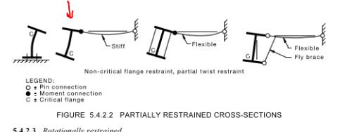
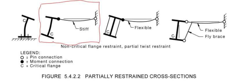
l = 4 ft or 48" = distance between points of partial restraint, assume we meet 2nd figure in figure 5.4.2.2
Capture_dljyi1.jpg


Kt = 1 + 2 (di/l) (tf/2 tw)^2 / nw (table 5.6.3(1) - PP restraint)
di = 23.625 in
l = 48 in
tf = 0.64 in
tw = 0.46 in
nw = 1 (1 web)

Kt = 3.651

Kl = 1.4 (Table 5.6.3(2) - PP Restraint and Load at top flange)

Kr = 0.70 (Table 5.6.3(3) - PP Restraint at both ends)

le = Kt Kl Kr l = 171.74 in

Member Capacity using Section 5.6.1.1 Open Sections with equal flanges

The moment profile yields:
alpha,m = 1.71 (table 5.6.1 (1.35 + beta,m * 0.36, where in this case beta,m = 1.0))

Ms = Zx Fy = 244 in3 x 50 ksi x 1 ft/12 in = 1016.67 ft-k

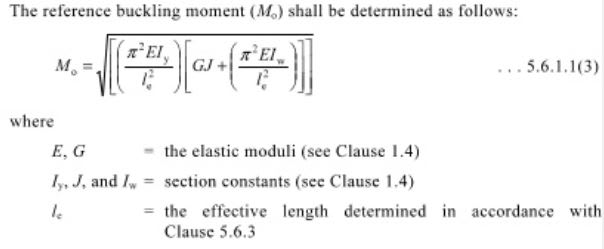
Mo:
Capture_qxiukn.jpg

where Iw = Cw in AISC = Warping Constant
E = 29000 ksi
G = 11200 ksi
Iy = 106 in4
le = 171.74 in
J = 2.81 in4
Iw = Cw = 17900 in6

Mo = 14527.68 in-k * 1 ft/12 in = 1210.64 ft-k

Ms/Mo = 0.84

alpha,s:
Capture_u1tfdx.jpg


alpha,s = 1.085

Mb = alpha,m alpha,s Ms <= Ms (eq. 5.6.1.1(1))
Mb = 1.71*1.085*1016.67 = 1886.3 ft-k <= Ms = 1016.67 ft-k, Ms controls.

So considerably more capacity than my AISC approach.

Question I am left with on this is the detail for partial restraint shows a fixed connection to the tension flange, would standard composite construction satisfy the fixity requirement? If not then I'd say you'd fall into an unrestrained condition and land back at an unbraced length of 32 ft which from quick numbers following the same procedure in AS4100 yields only 443.31 ft-kips, or less than that of my current AISC approach.


Open Source Structural Applications:
 
steveh49 said:
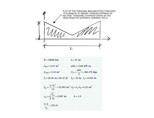
I think there might be a quick and easy first test we can apply. Taking the W27x84 and the same bi-linear shape of the moment diagram from the test case, I reduced the maximum bending moment to 1240 kNm which is the design section capacity phi.Ms. I then increased the sub-segment length until the AS4100 LTB capacity phi.Mb = phi.Ms. The sub-segment length was 5.065m (ie from end of beam to the inflection point) giving overall beam length of 20.26m before LTB governs according to AS4100.

If I may be so presumptuous, I believe KootK will have an opinion on whether this is realistic or not. If that opinion is that it is not, he may never 'drop his bone' and accept AS4100. That doesn't need to end the discussion but people may at least continue knowing that.

Firstly, please recognize that my only beef with AS4100 at this time is that:

a) I don't understand it on a theoretical basis and;
b) A room full of smart, AS4100 practitioners seem incapable of explaining it to me on a theoretical basis.

I presently have no concerns regarding AS4100's level of conservatism for LTB checking.

So on to the fun stuff. Your example was clever. Me likey. As I understand it, the crux of the example was to exaggerate the length of the original problem until constrained LTB did in fact occur; and, in doing so, suggesting that it would take a rather ridiculous span to make that happen (66.5 ft).

You have rightly presumed that that I would question whether or not your example was realistic. LTB is an abstract mathematical concept and, obviously, I don't have a "feel" for it as I have a feel for how far I can hit my seven iron into the wind. Moreover, whatever "feel" I do have for LTB is irrevocably tainted by my long history with the AISC provision. So I'll not claim that I can challenge the reasonableness of your hyperbolic example on the basis of intuition alone.

So what can I do to challenge the reasonableness of your example?

1) I could run it in Mastan. I may do this eventually but I wouldn't hold your breath.

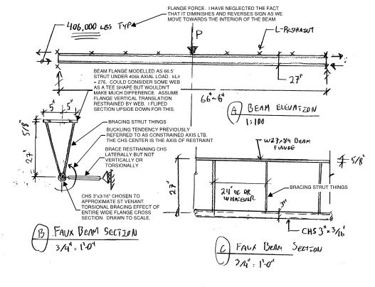
2) I could transmogrify your example into one of my own that I feel does an excellent job of teasing out the salient issues and placing them into a context in which "reasonableness" may more easily be judged via intuition. Truly, you'll have to just download the sketch and read the damn thing start to finish. Brief summary:

START

a) I assumed that bottom flange buckling is restrained by two, torsional stiffness components: the St. Venant and the Warping.

b) In the context of constrained axis buckling, the warping stiffness "is" the flange buckling laterally. So that's baked into the cake.

c) I replaced the St. Venant stiffness of the entire wide flange with a CHS member having nearly the same St. Venant stiffness. Everything is drawn to scale.

d) To make the thing tractable, I neglected some things such as the fact that the axial force in flange varies spatially. Still, it is a strut with 406K axial load applied to its ends.

e) The example considers the compression flange of the beam as a 66.5' flange-column having a slenderness ratio of 276. The flange-column would have axial compression loads to the tune of 406,000 lbs applied to the ends. This is actually more than the {As x Fy = 312k] of the flange. That's immaterial really though. 312k or 406k, it's a crap ton of of axial on a 66.5' column with a 276 slenderness ratio.

f) Naturally, we must consider that the flange-column is actually braced along it's 66.5' length. That bracing:

a) comes from the St.Venant torsional stiffness of the section;
b) varies linearly in it's effectiveness;
c) is at a maximum at near the supports and;
d) is at a minumum at the center of the beam.

This is what I have represented with the CHS section in the faux representation.

FINISH

So, assuming that I haven't screwed something up in my rush to pull this together, the question becomes:

How reasonable is it for us to expect that the 66.5' flange-column of my faux model will not buckle under a 406,000 lb load?

Seriously, what do you think?

EDIT: here's a dropbox link to the sketches in PDF format: Link. The file upload feature here is no longer working for me either.

c01_inf6wb.jpg

c02_eksdsg.jpg
 
Kootk said:
For physical, real world buckling, the top flange is out of play by definition as it is laterally restrained at such close intervals as to be continuously restrained. Ask yourself this: could the LTB buckling mode shown below physically occur with the top flange prevented from displacing laterally? If it can't, then top flange buckling has to be off of the table and the constrained axis LTB buckling would become critical.
Except constrained axis LTB buckling doesn't become critical. Beam yielding becomes critical because the load required for the buckling mode you are suggesting is off the charts.

By your logic you need to keep checking every critical buckling mode ad-infinitem.
 
Celt, the restraint you're assuming isn't classified as an L restraint. That's a P restraint. An L restraint is just preventing lateral deflection of the critical flange, not preventing twist. So only the restraint at 8' is effective, I've argued I'd only take the one at 12' being effective due to the proximity of the inflection point.

Alpha_s is less than or equal to one, if greater than one, set it to 1. Noted it doesn't expressly say this but it is implied based on what the factor represents.

Alpha_m is also only evaluated based on the segment length, not the entire member length. This will typically mean for shorter segments with little change in moment alpha_m being lower.

 
Human909 said:
Except constrained axis LTB buckling doesn't become critical. Beam yielding becomes critical because the load required for the buckling mode you are suggesting is off the charts.

Except that you are comparing apples and oranges. Beam yielding and LTB buckling are separate failure modes. Just because you hit yielding prior to constrained axis LTB, that does not mean that constrained axis isn't the critical LTB buckling mode. It just means that LTB doesn't govern the failure of the particular situation that you're considering.

Human909 said:
By your logic you need to keep checking every critical buckling mode ad-infinitem.

Yes, and this is precisely what we do using AISC. You know, if we replace ad-infnitem with "just stop someplace reasonable". A reasonable place to stop, for example, would be any buckling mode indicating a capacity higher than yield.

For the third time now, would you answer the challenge below:

Human909 said:
If you would please respond to this challenge, I'm fairly certain that I can convince you of the correctness of my reasoning in this. Please. This is one aspect that should be very easy to resolve.

KootK said:
A challenge for you Human909: sketch me a single bucking mode that would be further up the list in terms of its eigenvalue and could possibly occur in the presence of the lateral restraints. Just one.

 
Agent666 said:
Celt, the restraint you're assuming isn't classified as an L restraint. That's a P restraint. An L restraint is just preventing lateral deflection of the critical flange, not preventing twist. So only the restraint at 8' is effective, I've argued I'd only take the one at 12' being effective due to the proximity of the inflection point.
Probably should have said I looked at the segment from 4' to 8' which looks to only classify as P restraint on either end, which is why I chose that segment.
All the definitions for L restraint seem to contain a "and act at the critical flange" clause, so seems I'd agree with you that the first x in KootK's sketch that could count as L bracing would be at 12', so my take on the lateral bracing classification across the beam would be:
F P P L L L P P F


Agent666 said:
Alpha_s is less than or equal to one, if greater than one, set it to 1. Noted it doesn't expressly say this but it is implied based on what the factor represents.
Rereading that makes total sense that this should be limited to 1

Agent666 said:
Alpha_m is also only evaluated based on the segment length, not the entire member length. This will typically mean for shorter segments with little change in moment alpha_m being lower
yep solid catch I ran the calc over the full length first and whiffed on this the second time thru.

Open Source Structural Applications:
 
steveh49 said:
Regarding the discussion of Kl=1.0 for top flange loading from 14 Nov 16:40 to 19:30, I thought the lateral restraint at the load location removes the tendency of the additional ('p-delta') torque to exacerbate the twist and promote instability. By being sufficiently stiff to qualify as a lateral restraint, it provides sufficient horizontal force above the shear centre to counteract the destabilising torque. Possible alternative view: the lateral restraint moves the point of rotation very close to the top flange and the vertical load has ~zero lever arm about the point of rotation despite the shear centre kicking sideways relative to the top flange.

I disagree. Following your lead, I'll try to persuade by way of a hyperbolic example.

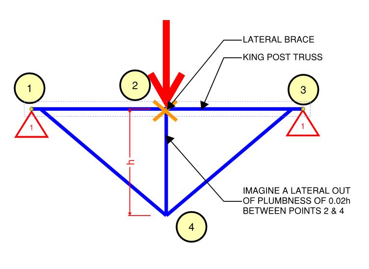
Would you say that the lateral brace at [2] makes this truss immune to LTB? Of course you wouldn't. But wait, isn't this different because it lacks rotational restraint at the ends?. Nah, not fundamentally. The rotational restraint at the ends increases the resistance offered to LTB but does not eliminate the fundamental tendency towards LTB. We could do something similar with a flat truss having end rotational restraint but it would take me all night to do a decent job of the buckled shape.

c01_r6owd9.jpg
 
I had more errors so made a quick spreedsheet to avoid some calculator mistakes:

For Segment 0 to 4 ft - Bottom flange critical:
Code:
Mm = 	1000	x1.7	1700
M2	872	XM2	760384
M3	750	XM3	562500
M4	625	xM4	390625
			
alpha,m	1.298690688		

segment L	4	ft	48	in		
						
Segment End Bracing						
0	F					
L	P					
	FP	1				
						
5.6.3 Effective Length						
						
Kt = 	1.166	Table 5.6.3(1)				
di = 	23.625	in				
l = 	48	in				
tf = 	0.64	in				
tw = 	0.46	in				
nw = 	1					
						
Kl = 	1.4	Table 5.6.3(2)	[b]assumes end reaction as segment load applied at bottom flange[/b]			
						
Kr = 	1	Table 5.6.3(3)				
						
Le = 	78.335	in				
						
5.6.1.1 - Open Section with equal flanges						
						
alpha,m = 	1.298	[calculated above]				
						
E = 	29000	ksi				
G = 	11200	ksi				
Iy = 	106	in4				
J = 	2.81	in4				
Iw = Cw = 	17900	in6				
						
Mo = 	65449.2	in-k	5454.10	ft-k	eq. 5.6.1.1(3)	
						
Zx = 	244	in4				
Fy = 	50	ksi				
						
Ms = 	12200	in-k	1016.67	ft-k	5.2.1	
						
Ms/Mo = 	0.186					
						
alpha,s = 	0.933	eq. 5.6.1.1(2)				
						
Mb = 	1231.73	ft-k	<=	Ms = 	1016.67	ft-k
Mb,use = 	1016.67	ft-k

Segment 4 ft to 8 ft - Bottom flange critical:
Code:
segment L	4	ft	48	in		
						
Segment End Bracing						
0	P					
L	P					
	PP	2				
						
5.6.3 Effective Length						
						
Kt = 	1.331	Table 5.6.3(1)				
di = 	23.625	in				
l = 	48	in				
tf = 	0.64	in				
tw = 	0.46	in				
nw = 	1					
						
Kl = 	1	Table 5.6.3(2)	[b][u]assumed 1 as no load applied in segment[/u][/b]			
						
Kr = 	1	Table 5.6.3(3)				
						
Le = 	63.907	in				
						
5.6.1.1 - Open Section with equal flanges						
						
alpha,m = 	1.75	table 5.6.1				
						
E = 	29000	ksi				
G = 	11200	ksi				
Iy = 	106	in4				
J = 	2.81	in4				
Iw = Cw = 	17900	in6				
						
Mo = 	97738.5	in-k	8144.88	ft-k	eq. 5.6.1.1(3)	
						
Zx = 	244	in4				
Fy = 	50	ksi				
						
Ms = 	12200	in-k	1016.67	ft-k	5.2.1	
						
Ms/Mo = 	0.125					
						
alpha,s = 	0.967	eq. 5.6.1.1(2)				
						
Mb = 	1720.51	ft-k	<=	Ms = 	1016.67	ft-k
Mb,use = 	1016.67	ft-k

Equivalent AISC check of entire span as L for bottom flange:
Code:
segment L	32	ft	384	in		
						
Segment End Bracing						
0	F					
L	F					
	FF	0				
						
5.6.3 Effective Length						
						
Kt = 	1.000	Table 5.6.3(1)				
di = 	23.625	in				
l = 	384	in				
tf = 	0.64	in				
tw = 	0.46	in				
nw = 	1					
						
Kl = 	1.4	Table 5.6.3(2)				
						
Kr = 	0.7	Table 5.6.3(3)				
						
Le = 	376.320	in				
						
5.6.1.1 - Open Section with equal flanges						
						
alpha,m = 	1.71	table 5.6.1				
						
E = 	29000	ksi				
G = 	11200	ksi				
Iy = 	106	in4				
J = 	2.81	in4				
Iw = Cw = 	17900	in6				
						
Mo = 	3806.9	in-k	317.25	ft-k	eq. 5.6.1.1(3)	
						
Zx = 	244	in4				
Fy = 	50	ksi				
						
Ms = 	12200	in-k	1016.67	ft-k	5.2.1	
						
Ms/Mo = 	3.205					
						
alpha,s = 	0.263	eq. 5.6.1.1(2)				
						
Mb = 	457.00	ft-k	<=	Ms = 	1016.67	ft-k
Mb,use = 	457.00	ft-k


Open Source Structural Applications:
 
I think this is the check you mention Agent
segment = 0 ft to 12 ft or from support to first brace point that could be considered an L brace.

Code:
segment L	12	ft	144	in		
						
Segment End Bracing						
0	F					
L	L					
	FL	0				
						
5.6.3 Effective Length						
						
Kt = 	1.000	Table 5.6.3(1)				
di = 	23.625	in				
l = 	144	in				
tf = 	0.64	in				
tw = 	0.46	in				
nw = 	1					
						
Kl = 	1	Table 5.6.3(2)				
						
Kr = 	1	Table 5.6.3(3)				
						
Le = 	144.000	in				
						
5.6.1.1 - Open Section with equal flanges						
						
alpha,m = 	1.3	table 5.6.1 [b]first figure in table with beta,m = -0.5 - M0= -1000 M12 = 500[/b]				
						
E = 	29000	ksi				
G = 	11200	ksi				
Iy = 	106	in4				
J = 	2.81	in4				
Iw = Cw = 	17900	in6				
						
Mo = 	20187.7	in-k	1682.31	ft-k	eq. 5.6.1.1(3)	
						
Zx = 	244	in4				
Fy = 	50	ksi				
						
Ms = 	12200	in-k	1016.67	ft-k	5.2.1	
						
Ms/Mo = 	0.604					
						
alpha,s = 	0.738	eq. 5.6.1.1(2)				
						
Mb = 	975.49	ft-k	<=	Ms = 	1016.67	ft-k
Mb,use = 	975.49	ft-k


Open Source Structural Applications:
 
Hey KootK. I think I might make this my last post because I don't think I'm my contribution is being constructive anymore. I appreciate your intrigue and knowledge and your persistance on this issue. [2thumbsup]

Kootk said:
Except that you are comparing apples and oranges. Beam yielding and LTB buckling are separate failure modes.
Correct. :)

Kootk said:
Just because you hit yielding prior to constrained axis LTB, that does not mean that constrained axis isn't the critical LTB buckling mode. It just means that LTB doesn't govern the failure of the particular situation that you're considering.
Precisely. But section 5.6 doesn't claim checking LTB it is a calculation for "nominal member moment capacity". The upper bound is by definition limitted by the section capacity.

Kootk said:
Yes, and this is precisely what we do using AISC. You know, if we replace ad-infnitem with "just stop someplace reasonable". A reasonable place to stop, for example, would be any buckling mode indicating a capacity higher than yield.
AS4100 stops at the section capacity. AKA when the beam starts yielding. This is also a pretty damn reasonable place to stop.

Kootk said:
For the third time now, would you answer the challenge below:
A challenge for you Human909: sketch me a single bucking mode that would be further up the list in terms of its eigenvalue and could possibly occur in the presence of the lateral restraints. Just one.
I thought I've answered that. There has never been any disagreement that if the top flange is FULLY restrained then the next up on the list is bottom flange buckling as you have illustrated. Christ I even posted a picture of it myself several dozen posts ago.
 
Human909 said:
I think I might make this my last post because I don't think I'm my contribution is being constructive anymore.

Stay. Your contributions could potentially be extremely constructive for me if you would only just indulge me and provide me with what I've been asking for:

KootK said:
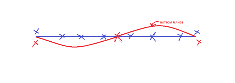
Ideally, I would have you each post a sketch similar to mine showing the expected movements of both flanges in plan.

How hard is it to just draw two colored lines and send that over to me? Surely, after all the effort that I've poured into assisting you here, you could do that much for me before your withdraw?

Human909 said:
There has never been any disagreement that if the top flange is FULLY restrained then the next up on the list is bottom flange buckling as you have illustrated.

This statement is basically saying that constrained axis lateral buckling IS the critical buckling mode. And that's in complete opposition to what you've been telling me for some time. What gives? If this means that your sketched, critical buckling mode would be identical to mine then please just say so. In that case, no sketch from you required.

Human909 said:
Christ I even posted a picture of it myself several dozen posts ago.

You've posted a ton of pictures. How on earth am I supposed to know which one you meant to answer my question with? Regardless, wouldn't reposting that picture -- or just giving me the two lines that I seek -- be far less effort that fighting me on this post after post?

Lastly, note that any buckling mode should have the beam pinned with respect to weak axis bending and the supports. Otherwise, it's not an apples to apples comparison with the base code methods. Your models seem to consistently show weak axis rotational fixity at the supports.

c01_o1mvng.jpg
 
I didn't see Kootk's bottom flange buckling mode in Human909's images, but Agent666 mastan2 results seem to show it.
 
celt83 said:
I think this is the check you mention Agent
segment = 0 ft to 12 ft or from support to first brace point that could be considered an L brace.

Yes, except there's a strength reduction factor of 0.9 to add in at the end that you've missed [bigsmile]

Beta_m is also positive when bent in double curvature, so alpha_m = 1.75+1.05*0.5+0.3*(0.5)^2=2.35.

So basically you have FLR as phiMbx = phiMsx (I.E. alpha_m * alpha_s >= 1.0.

Regarding your other checks, with AS4100/NZS3404 and the L restraints to the top flange, when the bottom flange is in compression, it's deemed the critical flange. Therefore the L restraint to the top flange is basically nothing and has no consideration. Therefore the first restraint to the critical compression flange is at 8' or 12' depending on your view.

So saying there is a P restraint at 4' isn't a correct approach.

Best way to think of it is as follows, just determine if a flange is in compression at the point of restraint and pickup the appropriate restraint. Noting an F restraint to the tension flange can be a P restraint in terms of the compression flange. But other than the designation changing an F & P are the same analytically for determine the effective length.

Code:
Top flange restraints 
FLLLLLLLF
F-------F
Bottom flange restraints

- = no restraint if the flange is in compression at this station.
 
When do people use P restraints? I can’t recall ever bothering with them.
 
KootK -
1.) Code stuff completely out the window, I have no problem thinking of the beam prior to being laterally restrained. Or rather, in the condition before I have provided anything but end restraint. I think of this as the first iteration. In this state I need to compare three numbers: moment at yield, moment at the critical (first) LTB mode, and the applied moment. If LTB is the critical failure mode, I add restraints to rule out that particular LTB mode. Can I stop here and say that yield is now the critical failure mode? No, because I need to know that the new critical LTB mode occurs at a higher moment than yield. Because of the added lateral restraint, LTB is changed, now the critical (first ) LTB mode is your constrained axis negative moment LTB. But is that the critical failure mode? I agree that it should be checked. For yield capacity to be claimed, LTB checking should be iterated (adding restraint and rechecking) until the critical LTB mode is shown to occur after yield.
Supposing constrained axis negative moment LTB occurs before yield, I might decide to add more restraint and check again. Something like this might be next:

ltb_xwacfc.png


I think you are dead on with this:
KootK said:
Yes, and this is precisely what we do using AISC. You know, if we replace ad-infnitem with "just stop someplace reasonable". A reasonable place to stop, for example, would be any buckling mode indicating a capacity higher than yield.

So when can we add restraint and call it a day?
 
Agent666 said:
Beta_m is also positive when bent in double curvature, so alpha_m = 1.75+1.05*0.5+0.3*(0.5)^2=2.35.
This is how I calculated it on my first pass but the diagram and range presented in table 5.6.1 seemed to suggest that the negative value should be used? Now looking at it again a value of -1 results in alpha,m of 1 which would align with the constant M diagram so seems the intent for moment reversal is positive beta,m and negative for just a change in end moment value but not sign.

Agent666 said:
So saying there is a P restraint at 4' isn't a correct approach.
so is it then a fair assumption to say that standard construction doesn't satisfy the P restraint condition indicated in figure 5.4.2.2, otherwise this would seem to be at odds with your statement?
Capture_fvveku.jpg


This all is turning out to be moot for the example KootK posed as everything is checking out above the yield moment.

Expanding to AISC where the definition of Lb is length between points that are either braced against lateral displacement of compression flange or braced against twist of the cross section, I think there is a rational argument to take the same 12' segment as Lb.

Cb:
x2.5 2500
Mmax 1000 x12.5 12500
Ma 625 x3 1875
Mb 250 x4 1000
Mc 125 x3 375

Rm 1

Cb 2.173913043
Capture_cfaplv.jpg


which has the same result of yielding being the controlling failure mode.


Open Source Structural Applications:
 
Celt83 said:
This all is turning out to be moot for the example KootK posed as everything is checking out above the yield moment.

Firstly, thank you for all of the effort that you've put forth in checking out my example, both in AS4100 and AISC. You did all of the work originally assigned to me and did it much thoroughly and more quickly than I would have. It's eased my burden substantially.

Secondly, once I get myself right with AS4100, I intend to never, ever again bother checking LTB on joist loaded floor girders unless they're cantilevered. This is clearly where AS4100 takes us to in the end. And it will be a nice little, lucrative take-away for me from this exercise. I postulate that the same may well be true of roof girders although owing to the same constrained axis effect even if the bottom flange is everywhere in compression.

Celt83 said:
Expanding to AISC where the definition of Lb is length between points that are either braced against lateral displacement of compression flange or braced against twist of the cross section, I think there is a rational argument to take the same 12' segment as Lb.

This will require us to have words however. What, exactly, is that rational argument, articulated in your own words as best you can? Is it purely semantic? Is it because considering L-restraint / constrained axis buckling clearly improves capacity? Or is there a theoretical reason, as I would hope?

I can't dispute that Le=12' is appropriate for AS4100 because I don't understand AS4100 on a theoretical basis. No theoretical understanding = not qualified to poke. I do, however, understand the AISC procedure on a theoretical basis and feel confident in saying that it is built around Lb being the distance between points that would be, in Aussie parlance, the distance between F/P restraints. I couldn't hope to explain that any better than the Yura paper did.

 
Tomfh said:
When do people use P restraints? I can’t recall ever bothering with them.

- I can't imagine that there are many practical opportunities

- My reading suggests that some folks may be attempting to do this in metal frame building by creating torsional connections between purlins and the rafters they would brace. I have no idea how much of this is happening out in the real world however.

- In temporary works, situations arise were you have somebody wanting to avoid stiffeners at the supports of a simply supported beam. This is a straight up no-no via AISC but, in the future, I'm hoping to use AS4100 P-restraints to make a go of it.
 
KootK said:
This will require us to have words however. What, exactly, is that rational argument, articulated in your own words as best you can? Is it purely semantic? Is it because considering L-restraint / constrained axis buckling clearly improves capacity? Or is there a theoretical reason, as I would hope?

From a purely semantic view the definition of Lb very specifically says "..points that are either braced against lateral displacement of compression flange or.."
so at 0' the bottom flange is in compression and braced at the support
in the range 0' < x <= 8' the bottom flange is the compression flange and unbraced
at 8' neither flange is the compression flange as this is the inflection point
at 12' the top flange is now both the compression flange and braced
so by a literal interpretation of the definition of Lb the unbraced length could be taken as 12'.

Reviewing all of the FEM results presented by Agent666 and Human909 this would seem to align with the buckling results they are getting.

My use of the full length for the bottom flange check was really just an extension of what you would do for a roof beam controlled by wind uplift, or put another way a beam that experiences negative bending across the full span. In this case I think AS4100 would seem to treat the beam identical to AISC.

I need to do a lot more reading/research/re-learning on my end to bring an approach founded in first principles to this though.

To really get a definitive answer on this, for use in my area, I've reached out to AISC to get their input on this specific example case relative to the determination of Lb, will post when I hear back from them.

Open Source Structural Applications:
 
HS_PA_EIT said:
I think you are dead on with this

Do you practice with AS4100 regularly?

Your agreement is a mixed bag for me. One the one hand, it feels great to have you agree with my position. On the other, this slows me down from possibly shifting my understanding to Human909's explanation of a single LTB procedure that deals with all buckling modes in one go.

The procedure that you described is exactly how I have seen things in the past. I would describe is as a hierarchical approach to LTB checking following this recipe:

1) Pick a beam such that all of your non-LTB failure modes pass (yield, shear, deflection...)
2) Start LTB with no bracing at all or, alternately, any bracing that will be present for free.
3) Identify and assess the single critical buckling mode associated with physical reality of #2,
4) If LTB governs over the other stuff and capacity is insufficient, add one brace. Otherwise STOP.
5) Return to step 2, adding your new brace to the suite of bracing already present for free.

HS_PA_EIT said:
So when can we add restraint and call it a day?

This would be step #4 in combination, of course, with step #1.

This procedure brings me back to my questioning of the interpretation of 5.5.1.1 and, in particular, the importance of the word "that" in that clause. Given a hierarchical procedure like that described above I would revise step #4 as follows:

4) If LTB governs over the other stuff and capacity is insufficient, add one brace to the critical flange at the proposed location of the the brace. The critical flange shall be that flange which would move the most under LTB buckling at the location of the proposed brace with the restraining effect of all previously added braces accounted for. Otherwise STOP.

For example, in checking constrained axis LTB, you'd come to that already assuming the presence of all the top flange restraints. As such the only flange capable of moving would be the bottom flange. So the bottom flange would be the critical one across the entire length of the beam for this particular LTB mode which is, of course, exactly as it would have to be if one were seeking to add a bottom flange brace in order to progress to the next possible LTB buckling mode.

What I find particularly interesting about 5.5.1.1 is that, in my opinion, a literal read of that clause should suggest exactly the interpretation that I've outlined. No "bending to my will" required. Were I a martian spending my first day on earth, my interpretation is how I would read 5.5.1.1 from the get go. I was surprised to learn that it is not, in fact, interpreted as I have outlined.

c01_xyng4f.jpg
 
Status
Not open for further replies.

Part and Inventory Search

Sponsor