Continue to Site

Eng-Tips is the largest engineering community on the Internet

Intelligent Work Forums for Engineering Professionals

  • Congratulations KootK on being selected by the Eng-Tips community for having the most helpful posts in the forums last week. Way to Go!

Rafter without fly brace? 22

Status
Not open for further replies.

fourpm

Industrial
Oct 12, 2019
13
I am designing rafters to AS4100 and wondering what if I don't use fly brace. I understand that with fly brace it will give you full restraint. But if I don't use fly brace, will the purlin above be considered as lateral restraint for rafter under uplift? If so. can I take the purlin spacing as segment and the only factor that changes without fly brace is kt?
I have the same question when it comes the continuous steel floor beam design where Z/C floor joints sit on top of the beam. What segment should I take for the beam near the support? Can I take the floor joists spacing as segment with lateral restraint? Can anyone give me some examples? I have read some manuals but the examples they have are simply supported beams only. Thank you.
 
Replies continue below

Recommended for you

Thanks for posting those buckled shapes.

How have you modelled the beam?
 
Does mastan2 work the same as microstran? same buckling answers?
 
Maybe, never tested if it can do flexural buckling. But it should give the same axial buckling loads.

I'm pretty sure your more basic analysis packages like Microstran can't do flexural torsional buckling checks, they only tend to be able to do axial buckling check (definitely SpaceGass can only do axial buckling unless I've been missing something all these years I've been using it!).
 
@steveh49:

I have more interesting ground that I want to cover here but I believe that I need a fresh, AS4100 familiar debate partner in order to move things forward productively. Lately I've had too many questions go unanswered and too many ideas left unexplored. The ROI on my investment here has been waning.

Would you be willing to explore some things with me here for a few more volleys? Perhaps half a dozen? I'm in no hurry. If you could attempt to respond even once per week, that would be perfectly adequate.

Do you practice with AS4100 regularly? For some reason, I had it in my head that you were based in the Netherlands.
 
Human909 said:
I'm almost become a little bored of this discussion.

I need you back in the pool for at least one more thing. Pretty please...

Human909 said:
In the cases I've seen so far 'mode 2' as you call it is significantly higher and not within the realm of being critical.

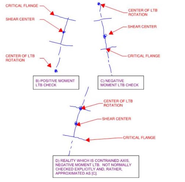
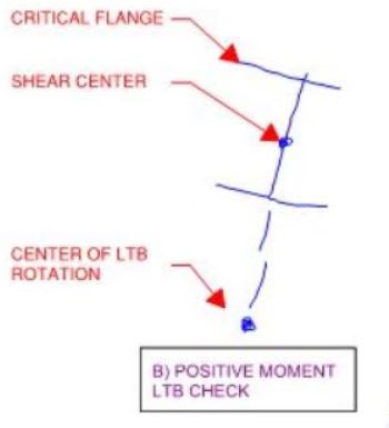
To recap, mode two is shown below and is what I have been referring to as constrained axis buckling. And it would indeed have a substantial capacity; I don't dispute that.

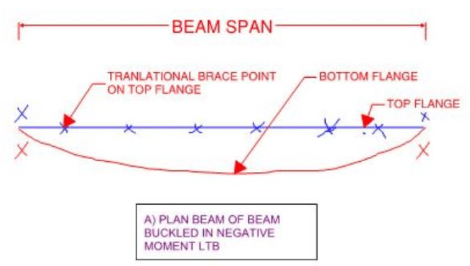
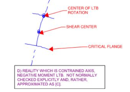
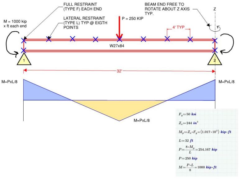
In my opinion, one cannot approach any LTB assessment without first having a buckling mode in mind to assess. For OP's problem, and for my W27x84 test case, the buckling mode shown below is the one that I believe is critical and the one that I would mean to assess, either via constrained axis buckling or, far more commonly, by running a negative moment LTB check on a beam with no intermediate restraints as Celt83 did in his analysis. This is what is commonly taken to be the AISC approach and I acknowledge it as a lower bound solution rather than an especially accurate one.

@ Human909 & steveh49. My question to you both is this: when you check LTB for the something like the W27x84 test case via AS4100, what IS the mode of buckling that you feel you are checking? Seriously. Ideally, I would have you each post a sketch similar to mine showing the expected movements of both flanges in plan. If that's not in the cards, please provide a verbal description. I'll attempt to translate any such descriptions into sketches for your approval.

This may seem trivial to the point that you wonder whether or not I'm attempting to poke fun at you. I assure your that I am not. We seem to have a fundamental disagreement here on what I consider to be the root starting point for LTB checking. Once I understand the source of this discrepancy, I may gain an important new insight into the inner workings of AS4100 which, presently, I find baffling.

c01_foyv1e.png

c02_bwa8mt.png
 
Thanks very much, Agent.

So the AS4100 hand method gives alpha_m * alpha_s * phi.Ms = 2009 kNm using Human909's Space Gass numbers from 14 Nov, but the elastic buckling analysis gives about 1240 kNm. 62% unconservative it seems.

Compared to Celt83's AISC capacity, 719 kNm/1240 kNm = 59%. AISC seems quite conservative. If the Cb factor were 3.31, AISC would give the same as the AS4100 elastic buckling method used by Agent666. This is right in the range suggested by Yura (probably a similar method as used by Agent666).

In practice, it would seem that the AISC requirement to restrain both flanges near an inflection point has a lot going for it.

KootK said:
Do you practice with AS4100 regularly?
AS4100 is my local code but I do far more concrete work. I like to participate in steel topics here to avoid forgetting everything. LTB stability is less of an issue for concrete so I've never developed an in-depth theoretical understanding.

Buckled shape for the test case: I'd have guessed similar to your sketch but straighter in the middle where the bottom flange is in tension. You were drawing a sine wave? (Which is pretty straight towards the middle, but I think straighter still.) Cheating by looking at Agent's pictures, it looks as though the load at midspan is stabilising that point which makes sense to me as the section must rotate about the restrained top flange so the shear centre load tries to restore the section to upright.

KootK said:
the inner workings of AS4100 which, presently, I find baffling.
AS4100 has two unconservative strikes in my book for its LTB capacity check. I may double check to AISC for anything that's not a doubly-symmetric section, or relies on L restraints.

{There is no attachment. I can't get rid of this box.}
 
 :
Kootk said:
This may seem trivial to the point that you wonder whether or not I'm attempting to poke fun at you. I assure your that I am not. We seem to have a fundamental disagreement here on what I consider to be the root starting point for LTB checking. Once I understand the source of this discrepancy, I may gain an important new insight into the inner workings of AS4100 which, presently, I find baffling.
I don't think it is trivial and I do think there is a fundamental conflict in your approach (and the AISC approach, though I still haven't taken the time to familerise myself with this.) Your approach seems more thorough, though it isn't yet clear that much is gained from this thoroughness. In outlier cases I would not be surprised if AS4100 is unconservative. Though at this stage I have yet to see that and AISC approach of ignoring all lateral restraints for bottom flange buckling is overly conservative.


Kootk said:
@ Human909 & steveh49. My question to you both is this: when you check LTB for the something like the W27x84 test case via AS4100, what IS the mode of buckling that you feel you are checking?
Given there are infinite modes, AS4100 isn't checking for any specific one. The code is designed so that if followed, then any feasible buckling mode is not going to occur.. From what I can tell the proscriptive rules of the code achieves this, though I'd love to see an example of where it fails.

You seem to be fixated on the bottom flange buckling mode. But in the examples discussed this buckling mode is many eigenvalues down the list and signficantly more difficult and unlikely to occur.

Kootk said:
Seriously. Ideally, I would have you each post a sketch similar to mine showing the expected movements of both flanges in plan. If that's not in the cards, please provide a verbal description. I'll attempt to translate any such descriptions into sketches for your approval.
As above you seem fixated on the notion that a codified buckling check needs to focus on ONE buckling mode. That is a bit inefficient really. A check that covers ALL buckling modes is more efficient, if such a beast is achievable. Thus a drawing like what you want is impossible.

AS4100 sets a threshold where if it is doing its job properly NONE of the buckling modes will occur.
 
I need that sketch. Does the file name have any spaces in it? The system here chokes on that. It needs to be blah_blah_date kind of file name. Alternately, email it my way and I can post it.

steveh49 said:
I'd have guessed similar to your sketch but straighter in the middle where the bottom flange is in tension. You were drawing a sine wave?

I'd not really gotten into that level of detail as to whether it was a sine wave or had a flattish spot. It definitely does have a flattish spot as Yura touched upon.

Your answer surprises me though in comparison to the comments of others. Based on your desicription it sounds as though you see the critical buckling mode being checked as being the constrained axis model that I've described. Human909 and Tomfh have both made statements suggesting that model is not the critical buckling mode being LTB checked in the AS4100 procedure.

 
steveh49 said:
So the AS4100 hand method gives alpha_m * alpha_s * phi.Ms = 2009 kNm using Human909's Space Gass numbers from 14 Nov, but the elastic buckling analysis gives about 1240 kNm 62% unconservative it seems.
Sorry. What? How do you figure this?

Kootk said:
Your answer surprises me though in comparison to the comments of others. Based on your desicription it sounds as though you see the critical buckling mode being checked as being the constrained axis model that I've described. Human909 and Tomfh have both made statements suggesting that model is not the critical buckling mode being LTB checked in the AS4100 procedure.
Why would you want to check a mode of buckling that occurs at a load approximately 10x past the point of the beam yielding? It makes not sense!

The 10x doesn't account for realworld imperfections etc. So lets call it 5x. We still are talking about checking for something that is not going to occur!

Better yet put a lower bound on the entire set of buckling modes which is what AS4100 tries and largely suceeds in doing. Though it probably should follow New Zealands approach in treating both flanges as critical in cantilevers. The buckling modes here are much closer together.
 
Human909 said:
Your approach seems more thorough, though it isn't yet clear that much is gained from this thoroughness.

The AISC approach is a good deal less thorough in my opinion. Relative to AS4100, I would describe it as more conservative and much simpler. Obviously, it's no surprise that those two features travel in tandem.

Human said:
You seem to be fixated on the bottom flange buckling mode. But in the examples discussed this buckling mode is many eigenvalues down the list and signficantly more difficult and unlikely to occur.

This is the part that strikes me as being hugely in error. Of course I'm focused on the bottom flange bucking mode. Given that the top flange is effectively continuously braced, there is no possibility of top flange buckling. So, in practical terms, is bottom flange buckling not the only mode of buckling in play here?

A challenge for you Human909: sketch me a single bucking mode that would be further up the list in terms of its eigenvalue and could possibly occur in the presence of the lateral restraints. Just one.

Human909 said:
As above you seem fixated on the notion that a codified buckling check needs to focus on ONE buckling mode. That is a bit useless really. You need a check (or many checks) that covers ALL buckling modes.

Yes! So consider:

1) In North America, being the ignoramuses that we are, we have an LTB checking procedure that checks just one lousy buckling mode at a time. We're the Homer Simpsons of LTB.

2) In AU, apparently, you've devised an LTB checking procedure mode that somehow checks ALL buckling modes simultaneously. This is a pretty good trick.

Given this, just imagine how magical the AS4100 procedure seems to North American eyes? Just imagine how badly we'd like to know how this magical procedure works??

But alas, so far no one has explained how it works so magically. And that is why I keep asking questions targeted at finding out. Once I understand this piece of the puzzle, I suspect that most of the rest will just fall into place.

Given that your a practitioner of this incredible, all in one, LTB checking method, do you yourself not feel an onus of responsibility to understand how it manages to check all possible buckling modes in one go?

Don't get me wrong, my issue here is not that I question whether or not AS4100 LTB works. My issue is that I don't understand how it works and, frankly, my impression thus far is that I am far from being alone in my ignorance. If you strip out my contributions, this thread reads something like:

-49% trying to interpret AS4100 clauses like the book of genesis.
-49% swapping FEM models to justify our interpretations of the book of genesis.
-2% discussing the actual theory behind AS4100 LTB methodology.

Does the dirth of theory talk not strike you as completely out of proportion here? It certainly does to me and I think that bespeaks an issued that I tabled earlier:

KootK said:
My impression here is that many of us, myself included, lack a cogent theoretical understanding of just how the AS4100 provisions work their magic. If we had such an understanding, I don't think that we'd be 160+ posts into trying to reconcile our differences on what should be entry level stuff. Instead, we'd just point to our cogent theoretical model and agree that "yup, it must be like this otherwise it wouldn't agree with the theory".

I'd hoped that statement would goad somebody into ponying up with a "screw you KootK, the theory is simple and HERE. IT. IS!". But no, just radio silence on that. Instead, everybody wants to keep telling me how simple AS4100 is to apply. I don't care if it's bloody Sesame Street simple to apply. If nobody actually understands the root theory that under pins the application, no amount of simplicity can rectify that in my opinion.

 
KootK said:
Given that the top flange is effectively continuously braced, there is no possibility of top flange buckling. So, in practical terms, is bottom flange buckling not the only mode of buckling in play here?
But that is the thing. The bottom flange buckling isn't in play, the beam will yield before it is in play. In occasions where it comes into play for example at a moment reversal such as a support that has no lateral or rotational restraint then AS4100 covers that too as the AS4100 would require restraints on the bottom flange to the effective length or alternatively the design capacity is reduced.

But like is insisted upon time and time again. AS4100 is a broad check. And if you have the critical flange continuously braced then you "advance to GO and collect $200." Why check for scenarios that aren't feasible?
 
Human909 said:
The bottom flange buckling isn't in play, the beam will yield before it is in play.

I believe this to be a logical error in your thinking on this. Just because a bottom flange buckling mode passes the LTB check, or another failure mode occurs first, that doesn't mean that bottom flange buckling wasn't the critical buckling mode to be checked in the first place.

Human909 said:
But like is insisted upon time and time again. AS4100 is a broad check.

Yes, this is has been insisted upon time and time again and proven theoretically exactly zero times. So I cling to my right to ask.

Human909 said:
Why check for scenarios that aren't feasible?

Because your only practical choices here are:

1) Check bottom flange buckling OR;
2) Check nothing at all.

If you would please respond to this challenge, I'm fairly certain that I can convince you of the correctness of my reasoning in this. Please. This is one aspect that should be very easy to resolve.

KootK said:
A challenge for you Human909: sketch me a single bucking mode that would be further up the list in terms of its eigenvalue and could possibly occur in the presence of the lateral restraints. Just one.
 
Human 909 & KootK - In the case of top flange lateral restraint, the bottom flange buckling (lateral and vertical translation) is resisted by the web. For the bottom flange to buckle, the web must fail. So which is the easier way for the beam, yielding in the bottom flange or bottom flange folding by bending the web? This will depend on the dimensions. Perhaps in reality yielding happens first 100% of the time, but I doubt it.

PS: I have watched this discussion intently and am very thankful to all contributors.
 
Human909 said:
.. In occasions where it comes into play for example at a moment reversal ...
I believe this is excatly the condition that KootK posted is it not?
Capture_azmvpi.jpg


Human909 said:
..AS4100 would require restraints on the bottom flange to the effective length or alternatively the design capacity is reduced.
so for the above beam are you indicating that AS4100 would treat this similarly to AISC and say that the unbraced length is 32'?

Open Source Structural Applications:
 
HS_PA_EIT said:
For the bottom flange to buckle, the web must fail

I disagree.

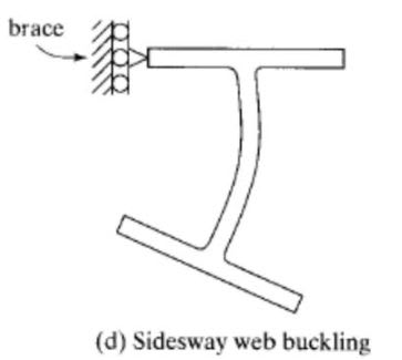
One way for the flange to buckle would certainly be for the web to fail in transverse flexure. And this sort of resembles a reaction / concentrated load phenomenon that we call web sidesway buckling in the North American parlance (first sketch below). Back in the spring of 2018, WARose and I hammered out what I suspect still stands as the definitive Rumble in the Jungle on that topic if you're curious to learn more: Link. In my opinion, it's next to impossible to generate this failure mode away from concentrated loads and reactions however.

Another, more likely, failure mode is shown in the second sketch below and taken from early on in this discussion. And it does not involve the failure of the web. About the same time that I first posted that sketch, I was describing LTB as:

KootK paraphrase said:
..rotation about a point in space above, below, or at the elevation of the shear center an horizontally in line with the shear center

I made a point of using that particular phrasing because I believe that it is the only, wholly accurate what to describe the physical phenomenon of lateral torsional buckling. That said, one can only repeat such a mouthful of jargon so many times before wanting to claw out their own larynx. So now I'm just using the more colloquial "bottom/top flange buckling" which seems to do a much better job of speaking to people's intuitions. It is important to recognize that there is a difference however.

In my next post, I'm going to do something nifty and related as it pertains to some of steveh49's previous work. It will also bear some similarity to celt83's previous work on flange buckling which has since been retracted. Stay tuned.

HS_PA_EIT said:
PS: I have watched this discussion intently and am very thankful to all contributors.

Welcome to the discussion; I very much look forward to your contributions.

c01_okndzy.jpg

c02_fiiumq.jpg
 
HU said:
For the bottom flange to buckle, the web must fail.

No, distortional buckling does not need to occur. The entire cross section can simply twist/warp (albeit with greater difficulty due to top flange being restrained horizontally).
 
KootK - I understand, I think my language was weak on that one. I can now see how a top flange lateral restrain could provide little to no resistance to twist, thereby allowing the beam to rotate as in your sketch D constrained axis negative LTB. Your concept of the center of rotation for LTB has been useful for me in thinking about this.

That looks like a good thread, I'll have to give it a read. Thank you.

I am questioning the following:
kootk said:
This is the part that strikes me as being hugely in error. Of course I'm focused on the bottom flange bucking mode. Given that the top flange is effectively continuously braced, there is no possibility of top flange buckling. So, in practical terms, is bottom flange buckling not the only mode of buckling in play here?
For determining the critical flange, don't you have to consider the "section" in the absence of any restraint for AS4100? I would think that because of this definition, either flange is in play. In this case perhaps there is some reasoning as to why the critical flange for a segment restrained at both ends is always the compression flange. I have a feeling that understanding what influences the center of rotation location (at centroid, above or bellow) for an unrestrained segment might hold the key.
 
Tomfh - I see that now. That was an error in my thinking/language (got to be careful with the word "must"). Thank you
 
HS_PA_EIT said:
Your concept of the center of rotation for LTB has been useful for me in thinking about this.

You couldn't imagine how good it makes me feel to hear that it's been useful to at least one person.

KootK said:
This is the part that strikes me as being hugely in error. Of course I'm focused on the bottom flange bucking mode. Given that the top flange is effectively continuously braced, there is no possibility of top flange buckling. So, in practical terms, is bottom flange buckling not the only mode of buckling in play here?

HS_PA_EIT said:
For determining the critical flange, don't you have to consider the "section" in the absence of any restraint for AS4100?

As you ponder my statement, it is absolutely crucial that you think only in terms of what you feel will actually happen, physically, in real life. No code talk. Once you start putting it into the context of AS4100 (or AISC), everything gets irrevocably muddied by:

1) Your assumption that your code is correct and;

2) Your assumption that your interpretation of your code is correct.

Those two things probably are correct. However, using them as a crutch form of theoretical evidence to prevents us from discussing the theory in a meaningful way. I've been battling exactly this effect for the better part of a month now.

HS_PA_EIT said:
I would think that because of this definition, either flange is in play

For physical, real world buckling, the top flange is out of play by definition as it is laterally restrained at such close intervals as to be continuously restrained. Ask yourself this: could the LTB buckling mode shown below physically occur with the top flange prevented from displacing laterally? If it can't, then top flange buckling has to be off of the table and the constrained axis LTB buckling would become critical.

A big part of what I'm striving to understand myself is how it can possibly make sense to make all of your LTB design decisions assuming an unrestrained system when, in fact, the actual, critical buckling mode will be anything but unrestrained. It would appear to be related to Human909's assertion that the AS4100 LTB checks actually preclude all relevant buckling modes as apposed to a particular mode.

c01_ffhcrz.jpg
 
Status
Not open for further replies.

Part and Inventory Search

Sponsor