Continue to Site

Eng-Tips is the largest engineering community on the Internet

Intelligent Work Forums for Engineering Professionals

  • Congratulations KootK on being selected by the Eng-Tips community for having the most helpful posts in the forums last week. Way to Go!

Rafter without fly brace? 22

Status
Not open for further replies.

fourpm

Industrial
Oct 12, 2019
13
I am designing rafters to AS4100 and wondering what if I don't use fly brace. I understand that with fly brace it will give you full restraint. But if I don't use fly brace, will the purlin above be considered as lateral restraint for rafter under uplift? If so. can I take the purlin spacing as segment and the only factor that changes without fly brace is kt?
I have the same question when it comes the continuous steel floor beam design where Z/C floor joints sit on top of the beam. What segment should I take for the beam near the support? Can I take the floor joists spacing as segment with lateral restraint? Can anyone give me some examples? I have read some manuals but the examples they have are simply supported beams only. Thank you.
 
Replies continue below

Recommended for you

Tomfh, no worries. Because as far as applying the standards provisions go, that's exactly what it says to do (rightly or wrongly). Theory is one thing, designing a beam in 4 minutes is another even if not theoretically correct, it will in all likelihood be conservative when you review the brutal curve fitting that went on in the alpha_s factor compared to real world beam behaviour. I used to have a book that had the derivation in it but for the life of me cannot find it again.

Which post exactly from human909 are we referring to here, so I can go back and review further to make sure I'm not missing the point and interpreting things the same or different to you? Given I don't know the moment diagram it can be harder to interpret his 3D printouts, also if I'm reading things right its not a elastic critical buckling analysis, more of an FEM thing, so need to explicitly model or allow for 2nd order effects (residual stresses, initial imperfections, plasticity). If you model these then you should get a similar answer to taking the results of the elastic critical buckling analysis and applying 5.6.4. Least thats the takeaway I took away from working through the mastan2 stability fun modules where they had some full FEM results from ADINA or something like that (from memory). Humans posted a nice picture but not 100% sure how he got to that point. I'm sure he can elaborate to add creedence to his analysis.

But I never recall seeing in any buckling analyses at a particular cross section the tension flange moving further than the compression flange (but to be fair never paid too much attention as not something that is important as you just want the reference buckling moment so you can apply CL5.6.4 requirements for real design). So it may happen, I'd have to go back and fish some old analyses out to see if I see this or not.

If you think you have a situation that warrants a buckling analysis, then you always have the option of doing a buckling analysis in AS/NZ standards.


Human mentions in his post:

human909 (Structural)11 Nov 19 09:13

Human said:
The code allows you to perform buckling analysis OR follow the suggested guideslines. It doesn't suggest that the results will be identical.


Human909, any comments?


That's because buckling analysis is directly working out the reference buckling moment from the buckled shape corresponding to your restraints, loading, etc. Where as via calculation you're estimating the effective length via all the k factors.

So because they are doing quite different things there will be some variation in the answers.
 
Agent666 said:
Which post exactly from human909 are we referring to here, so I can go back and review further to make sure I'm not missing the point and interpreting things the same or different to you? Given I don't know the moment diagram it can be harder to interpret his 3D printouts,
I tried to give a description with my buckling analysis. The moment diagrams are pretty simple to work out from the description. But even without any buckling analysis it is pretty clear that the compression flange isn't always the critical flange.
-As been previously discussed in most cases of a beam with restrained at both ends, the first mode of buckling will be full beam length with the top flange moving the furthest.
-A continuous beam or a beam that has fixed ends will have moment reversal.
-Thus the flange that moves the most won't always be the compression flange.


Agent666 said:
also if I'm reading things right its not a elastic critical buckling analysis, more of an FEM thing
It is 'buckling analysis', you can certainly do buckling analysis with FEM.
Agent666 said:
so need to explicitly model or allow for 2nd order effects (residual stresses, initial imperfections, plasticity).
Yes that would be preferable, I haven't includede intial imperfections etc... But that won't really change things much for a basic beam. It simply will lead to overestimating the buckling point it won't fundamentally change the comparison.

Agent666 said:
Humans posted a nice picture but not 100% sure how he got to that point. I'm sure he can elaborate to add creedence to his analysis.
I though I added all the description necessary to aid this discussion but feel free to ask if you want.

eg
250UB31_efqrb8_swoec0.png

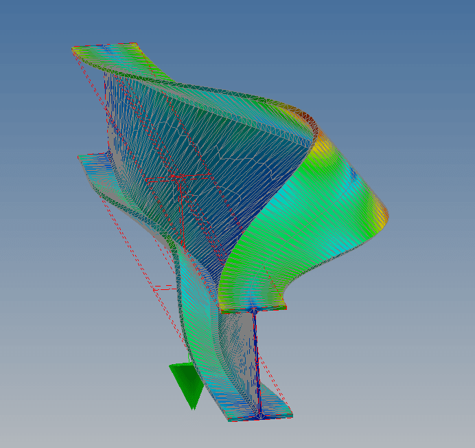
8m long 250UB31, fixed ends and centrally loaded. So a nice triangula moment curve with plenty of the beam having bottom flange compression. But the top flange is deflecting the most in the absence of restrains.
 
Human909:
With the absence of restraint in your model isn't the top flange deflecting the most in the region of the beam for which it is the compression flange? Also illustrating the point that an inflection point doesn't act as bracing.

Open Source Structural Applications:
 
Celt said:
With the absence of restraint in your model isn't the top flange deflecting the most in the region of the beam for which it is the compression flange

It’s a continuous beam so the top flange is in tension near the ends.

According to buckling analysis the top flange near the ends is critical flange.

According to compression flange definition the bottom flange near the ends is critical flange (how most people and most software designs in practice).

 
Working with Aussies is the best. With the time zone difference, I to get start each day with a new batch of ideas to ponder. It's like Christmas every day. I gotta get myself copies of the other Aussie material standards.

Human909 said:
It doesn't. There are plenty of short cuts being undertaken by 4100 in this respect I think we can both agree on this. The next question are these shortcuts conservative or what situations are they not conservative.

1) That's the thing. For this particular issue, it would be unconservative 100% of the time by some degree. And that's why I find it a strange choice of presentation. One could have very easily said something like this and been all the way good:

The load height factor shall apply to all segments extending out from the load until an F or P restraint is encountered.

2) With respect to "shortcuts", it actually appears to me that AS4100 is a likely more sophisticated, and accurate methodology than most of the others out there. It's just a matter of whether that extra sophistication is worth the cost which, inevitably, greater difficulty in specification and interpretation.

Human said:
Again complete agreement here. But that is not the approach of the code.

How do you know that it's the approach of the code? This is quite different from previous discussions where I was attempting interpretations that would alternatives to the obvious, literal interpretations. In this instance, however, it's almost the reverse. I would argue that my interpretation is the literal one and the one that is most linguistically accurate. It all comes down to the pesky "that section" bit shown below. The only wiggle room is whether or not the statement should read as:

1) Remove the restraint from that section assuming that all of the other restraints were there first and remain in place or;

2) Remove the restraint from that section assuming that all other restraints should be removed as well.

AS4100 said:
5.5.1.1 The critical flange at any cross section is the flange which, in the absence of any restraint at that section, would deflect the further during buckling.

If it is meant to be #2, why not just say "...the flange which, in the absence of any restraint applied within the segment, would deflect the further during buckling."

The reason that I keep harping on this is because I feel that this might be a candidate for resolving Tomfh's issue regarding the difference between the compression flange and the flange that moves the most. Just imagine the difference this would make to that if my interpretation were correct here? That said, as I've stated previously, I fully acknowledge that my being wrong about this is the most probable explanation.

If anybody could supply me with a published example suggesting that I am indeed wrong about this, I beg them to please do so. That way I could rule this out as a possibility and move on to more fruitful parts of the discussion.

Human909 said:
AS4100 is far from theoretically coherant as far as LTB goes.

I don't agree, at least not yet. As I said above, I suspect that AS4100 is likely the more advanced method theoretically. It's just much harder to understand which is, of course, unsurprising if it is in fact the more advance method. I'd give a thumb to be able to see a comprehensive derivation of the AS4100 method at this point. I feel as though I have that level of understanding with the North American provisions but most definitely do not have it with AS4100.

Human909 said:
If we want this thread to continue to be constructive I think we look for examples where AS4100 falls over for LTB. Because so far I haven't seen any issues apart from theoretical issues

We already have such examples:

1) Celt83's check resulted in an LTB capacity of only 50% of the plastic moment!

2) If AS4100 were run with what I would consider to be a reasonable effective length, it wouldn't reach the plastic moment either.

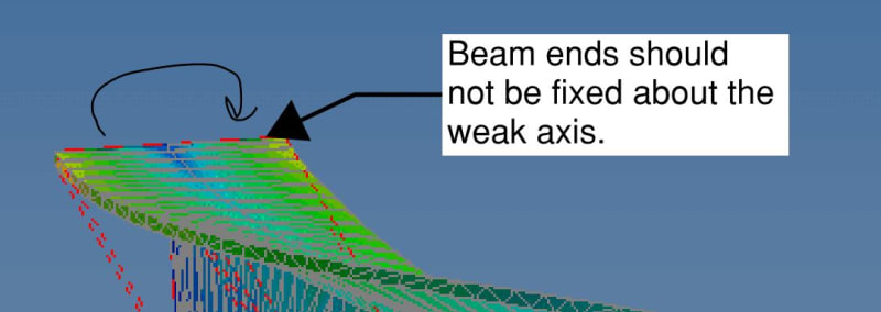
FEM isn't the be all and end all of this. It is very much about our interpretations of LTB methods and discrepancies in the results of those methods. Moreover, I think that you're FEM model needs to be changed in a very important way in order to be consistent with the codified LTB procedure. Yes, I get that there is often weak axis restraint to the beams ends in practice. But putting those as 100% fixed is going to neuter any comparison to the code procedures, particularly the AISC ones that give no explicit consideration to that.

c01_uvvjab.jpg
 
human said:
Yes that would be preferable, I haven't includede intial imperfections etc... But that won't really change things much for a basic beam. It simply will lead to overestimating the buckling point it won't fundamentally change the comparison.

Agree it won't change the overarching fundamental mode of failure. But it will affect your capacity quite a bit by including these things.


By critical buckling analysis I mean an eigenvector/eigenvalue type analysis (I forget which one exactly), mastan2 calls it elastic critical load. I believe you're doing the equivalent of a 1st or 2nd order elastic or inelastic check which requires the 2nd order effects to be allowed for. So if you haven't allowed for them in the output your mode of failure may be different so not clear if you would see the same tension flange thing going on (probably will).
 
Agent666 said:
We're all waiting on kootk's practical application of the AS4100/NZS3404 provision on his example first.

Firstly, you should't be waiting on it because two of my preconditions have not been met.

KootK said:
3) It's quite likely that I wont get to this until Xmas break. From now until Dec 31, I'm stuck in PDH Armageddon.

5) I'm going to probe AS4100 theory more deeply here before I dive in. I expect some real cooperation with that rather than defensive xenophobia.

It's obviously not Christmas and you in particular have been uncooperative. Instead of answering my direct questions, you seem to prefer to tell my why they're pointless.

Secondly, it's really a moot thing at this juncture anyhow as Human909 has graciously already completed the exercise at my direction as show below. That's it below with the key feature being Le=L and a moment capacity lower than the AISC method.

Human909 said:
Le=L As per KootK
AS4100 1998 CALCULATIONS FOR GROUP 1 (*=Failure)
------------------------------------

Critical load case is 1, out of 1

Section: *W27x84 (I or H section, Rolled/SR)

Failure Crit Start Finish Axial Major Minor Major Minor Load
Mode Case Pos'n Pos'n Force Shear Shear Moment Moment Factor

Section 1 0.000 0.00 0.00 556.03 -1355.82 0.00 0.91*
Member 1 0.000 9.754 0.00 -1355.82 0.00 0.40*
Shear 1 0.000 0.00 0.00 556.03 -1355.82 0.00 1.03
(1.00)

Grade= 50 Fy = 344.7 MPa
Fyw = 344.7 MPa Fu = 448.2 MPa
Ltot = 9.754 m Lseg = 9.754 m (FF Bot-Bot)
kt = 1.00 (5.6.3) kl = 1.40 (5.6.3)
kr = 1.00 (5.6.3) Le = 9.754 m (Bending) (5.6.3)
Lx = 9.754 m (Compression) Ly = 9.754 m (Compression)
Lz = 9.754 m (Torsion)
Ly/ry= 185.4 (Compression) Le/ry= 185.4 (Bending)

Arf = 0.0 mm^2 Arw = 0.0 mm^2
An = 15935.5 mm^2 Ae = 0.0 mm^2 (6.2.2)
Kf = 0.00 (6.2.2) Kt = 1.00 (7.3)
αm = 1.70 (5.6.1.1) αs = 0.26 (5.6.1.1)
αcx = 0.00 (6.3.3) αcy = 0.00 (6.3.3)
αb = 0.00 (6.3.3) βme = -1.00 (8.4.4.1)
βmx = 0.50 (8.4.2.2) βmy = 0.00 (8.4.2.2)
γ = 0.00 (8.3.4) ϕ = 0.90 (3.4)

N* = 0.00 kN
Vx* = 0.00 kN (not considered) Vy* = 556.03 kN
Mx* = -1355.82 kNm (Compact) My* = 0.00 kNm (Compact)

ϕNt = 0.00 kN (7.2) ϕNs = 0.00 kN (6.2)
ϕNcx = 0.00 kN (6.3.3) ϕNcy = 0.00 kN (6.3.3)
ϕNoz = 0.00 kN (8.4.4.1) ϕMo = 378.60 kNm (5.6.1)
ϕVvm = 876.75 kN (5.12) ϕMf = 847.98 kNm (5.12.2)
ϕMsx = 1240.57 kNm (5.2) ϕMsy = 161.68 kNm (5.2)
ϕMbx = 543.63 kNm (5.6) ϕMox = 0.00 kNm (8.4.4)
ϕMrx = 0.00 kNm (8.3.2) ϕMry = 0.00 kNm (8.3.3)
ϕMix = 0.00 kNm (8.4.2.2) ϕMiy = 0.00 kNm (8.4.2.2)
ϕMtx = 0.00 kNm (8.4.5.2) ϕMcx = 0.00 kNm (8.4.5.1)

Mx*
---- = 2.49 > 1.00* (Fail) Flexural-torsional buckling (5.6)
ϕMbx
 
Human909 said:
In the cases I've seen so far 'mode 2' as you call it is significantly higher and not within the realm of being critical.

Human909 said:
You have. But this aspect is largely not considered by myself or other users of AS4100.

Human909 said:
We haven't been contrained axis LTB for AS4100 because the code doesn't require you to consider this! In fact the code largely if not completely ignores constrained axis LTB.

I'm going to do my usual thing here and speculate wildly, risking probably having my ass handed to me when the dust settles.

1) I think that you and Tomfh have been checking constrained axis LTB (my mode 2) all along and you just don't yet realize it.

2) I think that when you check per AS4100, you are in fact checking constrained axis LTB which is why:

a) AS4100 may well be quite advanced theoretically and;

b) AS4100 LTB capacities come out high relative to AISC. They're not high because they're wrong; they're high because they're more right.

I'll expand on this later. I want that separate since, as I'm a glutton for punishment, I'll be seeking a broader consensus.

I have yet another request to ask of your generosity. Could you post a screenshot of the Spacegas input screen wherein you input the parameters that apply to your beam designs? I suspect that I might find utility in knowing just which parameters are input by the use as compared to those determined by the software.

 
Agent666 said:
...support group I'm setting up for Aussies and NZ'er who have been scarred by the process of taking 100+ post to convince a person how to apply the simple design provisions in our standards.

If they're so simple:

1) How come you and tomfh don't fully agree?

2) How come, clearly, there are other antipodeans lurking in the wings and seeing value in this discussion?

3) How come it's taking you 200+ posts to explain these simple provisions to me? Do you find me intellectually deficient in some way?

A DIRECT CHALLENGE TO YOU AGENT666:

If the AS4100 provisions are so simple, derive them and post the derivation here. Seriously. I've no doubt that this would answer all of our questions if you could pull it off. I certainly couldn't do this. To date, I don't even understand how it can be appropriate to treat a beam on a sub-segment by sub-segment basis when, clearly, physical buckling occurs across the full length between F/P braces. When I do find out why this is appropriate, I suspect that I'll have added a very valuable tool to my arsenal. Which is why I persist.

 
Tomfh said:
I’m not taking the piss.

While Tomfh and I often seem to be at cross purposes:

1) I feel that Tomfh's concern over the critical flange definition is of great importance.

2) I do not feel as though anyone has yet provided a robust answer to this concern.

3) Whether it seems so or not, much of what I've been up to is geared towards addressing this concern.

4) I wholeheartedly respect Tomfh's dogged instance that a robust answer to this be found. I would do the same.

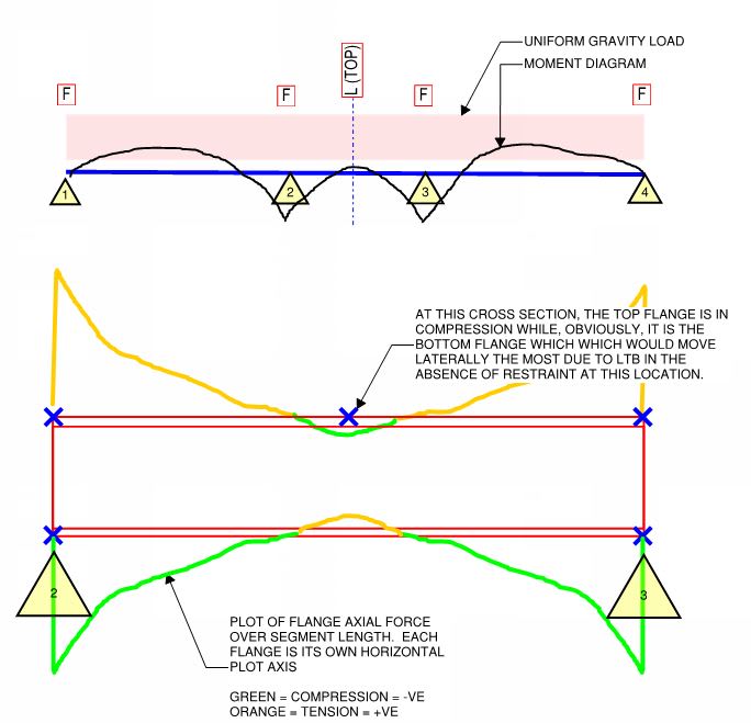
5) You don't need a computer to tell you that there are situations where the tension flange would be critical. You can prove it to yourself with a targeted mental experiment as shown below.

c02_fkjj3x.jpg
 
Applying them is simple. Numerous examples have been shown as to the intent of applying them. Stop putting words in my and others mouths.

I did have a book somewhere that went through the full derivation, but for the life of me cannot find it. Its somewhere in several thousand pdfs. I'll post it when/if I find it to see if it sheds any light on things theoretically.

I don't think you're deficient, quite the opposite. But a lot of threads here end with you going on and on and on until everyone gives up basically especially where others have opposing views to your own. Multiple people noted you weren't interpreting it correctly and you noted numerous times that the bulk of people saying this were wrong despite our protests to the contrary. Only when the examples were finally posted starting with the example you misinterpreted the flange restraint on did you start to realise what everyone was saying regarding the application. This process of confirmation/denile has directly contributed to being here 200 posts later, we've all been party to it.

People are simply trying to help you understand that L restraints have some effect in applying the provisions and also in the real world behaviour of beams, something which you seem to be coming round to based on the fact you've changing your tune a little to say our code possibly does things 'more right' than American equivalents.

You're trying to justify it with theory which is fine. That doesn't help me design anything in accordance with the standard though.

What I and others are fundamentally trying to understand is how you are intending to interpret the provisions with respect to the allowance for L restraints if you're not on board with the way myself and others interpret it. You simply stated human909s example did it the way you wanted. But he's ignoring the L restraints completely to the compression flange, which is hugely conservative compared to allowing for the additional restraint.

So here you're saying that they have no effect from a design standpoint. But standards are quite clear that they allow for this beneficial effect, so how would you apply the provisions as they are written is the point I thought you were going to clarify at some point? Because you didn't seem in full agreement with the way it was done in the other human909 example where the beam achieved FLR, but that might be on a theoretical level rather than a how do I apply the standards provisions level (which is pretty much the way most of us familar with the standard would approach it, as I noted I'd probably ignore the L restraint right at the inflection point, because a small variation in moment distribution could mean it's really attached to the opposite flange than your design intended in practical structures).

I'm not sure why Tom and myself aren't in agreement, but as I understand it we are in agreement with how to apply the provisions at least. He's simply questioning my direct interpretation of 'use the compression flange as critical flange no matter what'. I plan on looking at the tension flange going further thing in some buckling analyses. If it is the case then I'm with everyone else regarding the lack of connection between the standards definition.
 
Kootk said:
1) How come you and tomfh don't fully agree?

We only disagree on the precise relationship between the two methods for establishing the critical flange. Are they “one and the same”? Or are they alternative methods which give similar answers.

It’s a subtle question which makes no difference to our basic question of whether or not a top flange lateral restraint halves effective length for a continuous beam under gravity load.

Agent and I agree it does under AS4100. It’s how AS4100 is written and intended and how everyone who understands it uses it.


Agent666 said:
Stop putting words in my and others mouths.

Please show me some examples of this. If they exist, I would like the opportunity to apologize for them. These clearly do not qualify.

Agent666 said:
... scarred by the process of taking 100+ post to convince a person how to apply the simple design provisions in our standards.

KootK said:
If the AS4100 provisions are so simple....

Agent666 said:
...reading it any different is causing me to lose faith in the education system as far as reading comprehension is concerned.

KootK said:
Do you find me intellectually deficient in some way?

If you intended for those statements to be anything other than condescending and dismissive, it's your writing that needs work, not my reading.

Agent666 said:
But a lot of threads here end with you going on and on and on until everyone gives up basically especially where others have opposing views to your own.

I know this. I know it to my core. Hokie and Jayrod have both told me directly (and oddly identically) that I am like a dog with a bone. And those were not meant to be flattering descriptions, even if they were delivered with subtle decorum. I also suspect that valued member CELinOttawa no longer haunts this forum because I frustrated the living snot out of him on multiple occasions of which this was the last.

It brings me no joy whatsoever to know that many find me tedious and exhausting. That, especially when it's someone like you or Tomfh for whom I have a great deal of technical respect. I very much crave your approval and your camaraderie here on this forum. That said, I will absolutely forgo those things if that's the price of my continued, theoretical, truth seeking. I've got other friends and, frankly, need few. Don't cry for me Argentina.


[Edit: section above higlighted for the benefit of all those that I've annoyed before.]

1) This thread, and others in which I "go on and on", are clearly found to be of great value by some. Do you suppose that same value would exist if i didn't do as I do?

2) I feel that one of the biggest obstacles to meaningful discourse here is that smart people "agree to disagree" rather than putting forth the effort (and risking their egos) in order to reach consensus/resolution. I bloody hate "agree to disagree". This is applied physics, not human resources. There often are answers that are truly correct and can be found if we dig deep enough. This is why I stick with these things until I'm actually convinced that I'm wrong. And I do get to that point regularly. Part of the reason that I like sharing space with Tomfh, even though he offends me often, is that I feel that he is of a similar mind. He fights 'til he's burger... I respect that, even if he does not enjoy it.

3) As I've made clear previously, you are under no obligation to continue participating in -- or even following -- this thread. You can pack it in any time you like and be free of the frustration and tedium that comes along with debating me. I always get a kick out of this aspect of things. People who get frustrated by my "arguing" with them don't seem to realize that all they have to do to put an end to that is to stop arguing with me. But nobody ever wants to give up their claim to the last word. Instead, they seem to want me to throw in the towel first as some kind of preemptive capitulation to spare them the discomfort of having to give up themselves. Even if I wanted to do this, I don't know how on earth I'd be able to anticipate when to do this.

Agent666 said:
Multiple people noted you weren't interpreting it correctly and you noted numerous times that the bulk of people saying this were wrong despite our protests to the contrary.

I see nothing at all wrong with that. I thought you guys were wrong, I argued my case to the best of my ability, I personally posted the example problem that proved me wrong, and then I quickly acknowledged that I was indeed wrong. If you know of some way to prosecute a debate without expressing disagreement, fill me in. And of course I didn't accept that I was wrong because a handful of other folks said so. How would I, or anybody else, learn anything if I had? Yielding to greater numbers is polling, not discovering.

Agent666 said:
This process of confirmation/denile has directly contributed to being here 200 posts later, we've all been party to it.

Yes, but you seem to be overlooking the fact that many of us consider it a good thing that there are 200 posts here. I know that I certainly do. And several of the pseudo lurkers have only chimed in to voice their appreciation as well. It is a mistake to assume that, just because you find this tedious and frustrating, everyone else does too.

Agent666 said:
People are simply trying to help you understand that L restraints have some effect in applying the provisions and also in the real world behaviour of beams, something which you seem to be coming round to based on the fact you've changing your tune a little to say our code possibly does things 'more right' than American equivalents.

I never said that L restraints were not effective. In fact, I spoke to their effectiveness directly on the 23rd post of this 200+ post thread. And then three additional times after that.

KootK October 18th said:
6) As shown in sketch D below, our real world expectation is actually constrained axis buckling about the top of the beam. This usually has a higher capacity than sketch C but is a serious pain the the butt to calculate so we just go with sketch C and call that good enough.

KootK October 25th said:
b) If one desired additional capacity at the expense of additional complexity, one could consider constrained axis buckling to get more capacity as a result of the top flange lateral restraints.

KootK November 13th said:
1) It gets really, really hard to make something buckle via the constrained axis buckling model where the bottom flange swings upwards.

KootK November 13th said:
4) I would have calculated this as you have. That said, it's prudent to acknowledge that this method is not the constrained axis method which would yield a higher capacity.

KootK said:
6) As shown in sketch D below, our real world expectation is actually constrained axis buckling about the top of the beam. This usually has a higher capacity than sketch C but is a serious pain the the butt to calculate so we just go with sketch C and call that good enough.
________________

Agent66 said:
You're trying to justify it with theory which is fine. That doesn't help me design anything in accordance with the standard though.

Who says that I'm trying to help you design anything in accordance with the standard? I'm interested in the theoretical aspect of this so that's what I speak to. It's for me and OP, not you. I also contend that many engineers do see value in understanding the theory that underpins their code provisions. Were OP to chime in and say "knock it off KootK, I'm sick of hearing about the theory", I would bow out. That's not a decision that you get to make for the group however.


Regarding this mental exercise:-
c02_fkjj3x_jjpumf.jpg

I don't get why you are saying the flange axial force is at a maximum at the beam ends, when the moment is zero... but forgetting about that inconsistency for a bit:-I see what you did, it's a blowup of the middle span! Looking comprehension....

If I do a buckling analysis for a scenario like this, I get the top compression flange buckling the furthest at midspan where you proposed the L restraint. So I'm just never seeing this effect you are noting at that mid point of the middle span that the tension flange is buckling the furthest like you're stating/proposing?

But I am seeing in the negative moment region that the top flange in tension is moving further than the compression flange, which I assume is the point you're getting at? So in effect if you had an L restraint to the top flange in this region it is restraining the flange that appears to be moving the furthest (even though it was the tension flange).

But on a segment basis, the compression flange always is the one that goes the furthest overall.

Keep in mind for practical design you'd almost always be putting a restraint out in the middle somewhere where the compression flange is the one trying to go the furthest to get your best bang for buck in terms of equalising the effective lengths either side of a restraint location. Or alternatively aim to restraint the flange at the point where it wants to go the furthest

F restraints interpreted/applied to prevent lateral translation and twist of the cross section.

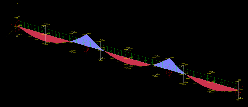
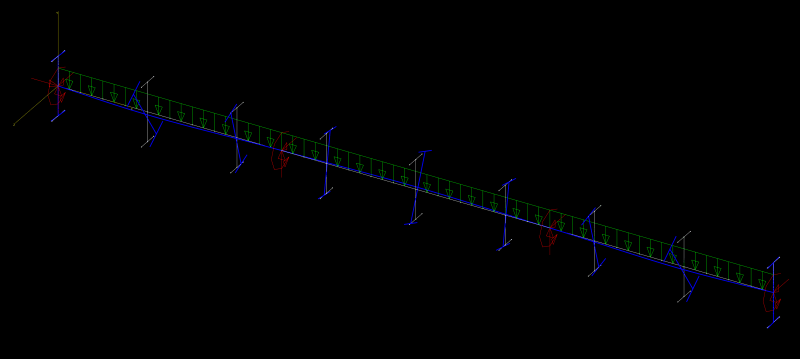
Refer screenshot below of the mom.ent, and displaced shape. I-sections added for visualising the twist and which flange moves the furthest. Click the link to download the full resolution image as hard to see details otherwise.
Capture_diagq7.png

LINK TO IMAGE
Capture2_j7baqr.png

LINK TO IMAGE
 
Agent said:
But on a segment basis, the compression flange always is the one that goes the furthest overall.

I still don’t understand what you mean by this. Human has posted screenshots which show segments with cross sections where tension flange buckles further than the compression flange, eg adjacent the supports in the unrestrained case.

 
Well if he provides the geometry/loading/restraint I'll try recreate the same scenario?

What I meant for clarification:-
For the middle span/segment in my images, of all the infinite number of cross sections making up that particular span/segment, the compression flange moves the furthest right at the middle in that segment. So on a segment by segment basis the compression flange always seems to move the furthest (based on a limited number of runs this morning playing around with it + previous experience on real world scenarios).

I didn't read any of his simply supported beam images like you did? Compression flange seemed to go the furthest? Please take his image and markup where you are specifically referencing so I'm interpreting your opinion correctly.
 
Status
Not open for further replies.

Part and Inventory Search

Sponsor