Continue to Site

Eng-Tips is the largest engineering community on the Internet

Intelligent Work Forums for Engineering Professionals

  • Congratulations waross on being selected by the Eng-Tips community for having the most helpful posts in the forums last week. Way to Go!

Rafter without fly brace? 22

Status
Not open for further replies.

fourpm

Industrial
Oct 12, 2019
13
I am designing rafters to AS4100 and wondering what if I don't use fly brace. I understand that with fly brace it will give you full restraint. But if I don't use fly brace, will the purlin above be considered as lateral restraint for rafter under uplift? If so. can I take the purlin spacing as segment and the only factor that changes without fly brace is kt?
I have the same question when it comes the continuous steel floor beam design where Z/C floor joints sit on top of the beam. What segment should I take for the beam near the support? Can I take the floor joists spacing as segment with lateral restraint? Can anyone give me some examples? I have read some manuals but the examples they have are simply supported beams only. Thank you.
 
Replies continue below

Recommended for you

Agent666 said:
is the decimal value correct? as just noticed many don't equal the imperial fraction.....

The decimal values are used for design, the fractions are used for detailing. ASTM A6 rolling tolerances allow for variation of the shape, which is why the values don't really match.
 
No idea why I bother spending hundreds on SE study materials, when I can just browse these threads in my free time and have a better understanding than I'd get to on my own.
 
@Human909: I have a brain teaser for you, knowing that you tend to view these things from an energy conservation perspective as I do.

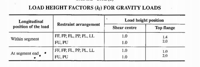
I take the table below as meaning that you only need to account for the destabilizing effect of vertical load position when the load is physically applied to the segment (mid-length or at the ends). I assume that this applies to sub-segments as well as full segments which seems to be consistent with your calculations.

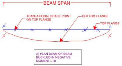
With respect to the W27 example, this would mean that the negative moment capacity check would be unaffected by load position (kl=1.0). Yet, when the bottom flange kicks out at mid-span as a result of negative moment LTB, the load will move closer to the earth because it is top flange loaded rather shear center loaded. This is because a load applied at a higher elevation will lower more for the same beam rotation. So how does this make sense from an energy conservation perspective? It's almost as though the design procedure assumes F restraint at the ends of all sub segments for this purpose.

c01_x3x3gn.jpg
 
The negative moment segment has no load applied to it, so yes k_l is taken as 1.0.

In the two central 4' segments either side of the applied load, with an LL segment with load applied at the end of the segment k_l is also 1.0 (irrespective of the load height). The load is constrained to act through the shear center. L restraint prevents lateral deflection of the critical top compression flange, in doing so the load cannot move laterally which is what this factor is accounting for. It has nothing to do with any movement of the tension (non critical) flange that may occur.


sbisteel, thanks for confirming that!
 
Human909 said:
Kootk I've updated the results. It changes the story a bit.

It does indeed. Now AS4100/AISC = 1.53 which is becoming a substantial discrepancy. And that's with the AS4100 capping out at yield. Take that cap off and I'm sure the discrepancy would be even greater.
 
Agent666 said:
The negative moment segment has no load applied to it, so yes k_l is taken as 1.0.

I get that's how the code reads. What I'm questioning is whether or not that's theoretically correct. It appears not to be.

Agent666 said:
The load is constrained to act through the shear center.

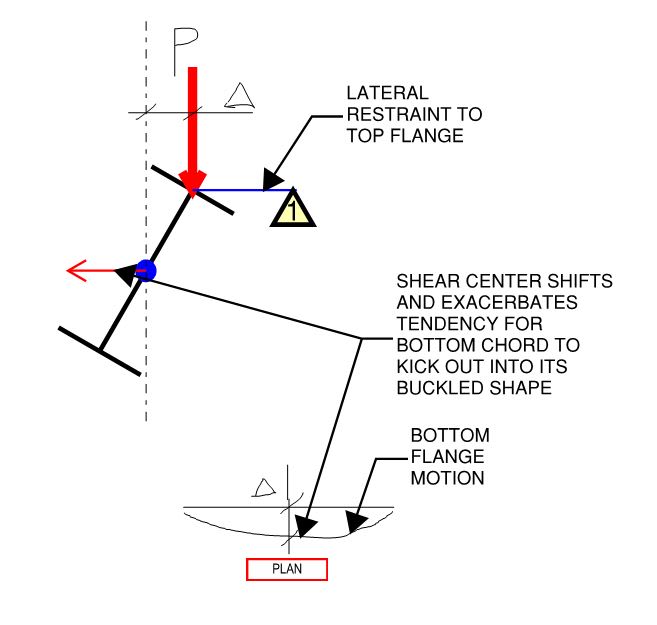
I don't believe that it is. When the bottom chord kicks out, the shear center moves. And that creates the same eccentricity as though the top flange had moved.

Agent666 said:
L restraint prevents lateral deflection of the critical top compression flange, in doing so the load cannot move laterally which is what this factor is accounting for.

Lateral motion of the load isn't really what the factor accounts for in my opinion. Much more precisely, what it accounts for is the eccentricity between the load and the shear center. Like a localized P-delta effect.

Agent66 said:
It has nothing to do with any movement of the tension (non critical) flange that may occur.

We clearly disagree on that.
 
I think the difference is that the tension flange wants to move back to where it was, whereas a compression flange with the load applied wants to carry on and buckle. So in effect the tension flange even if it moves sideways still reaches a new state of equilibrium that is not inherently unstable, apply more load and it tries harder to stabilise itself as opposed to wanting to get all unstable and so forth.


Its sort of similar to applying the load to the bottom flange below the shear center, tension flange is doing its best to help keep thing stable if you've prevented movement of the critical compression flange.


Agent666 said:
I think the difference is that the tension flange wants to move back to where it was, whereas a compression flange with the load applied wants to carry on and buckle.

I agree that the the tension flange would fight movement more than a compression flange. That said, the tendency for exacerbating bottom flange kickout still exists and, therefore, so does my minor concern with this.

Agen666 said:
So in effect the tension flange even if it moves sideways still reaches a new state of equilibrium that is not inherently unstable, apply more load and it tries harder to stabilise itself as opposed to wanting to get all unstable and so forth.

I don't see how you'd able to guarnatee that this is a self stabilizing system without putting numbers to it. That, particularly given that this effect constitutes an amplification of another instability (LTB) rather than a separate instability unto itself. Rather, you're evaluating an LTB + P-Delta condition with both effects in play concurrently.

Agent666 said:
Its sort of similar to applying the load to the bottom flange below the shear center, tension flange is doing its best to help keep thing stable if you've prevented movement of the critical compression flange.

I think that is a quite different situation. It's not just the tension flange trying to rectify beam rotation with the load below the shear center but, far more significantly, the load eccentricity itself that is attempting to rectify the beam rotation.

c01_nb5wga.jpg
 
Agree the load height factor accounts for buckling P-delta effect as opposed to whether or not it causes tension or compression.
 
An additional thing that occurred to me over lunch is that, while our example beam bottom flange is in tension beneath the load, it switches to compression before the end of the beam. This would have some effect on this:

Agent666 said:
I think the difference is that the tension flange wants to move back to where it was, whereas a compression flange with the load applied wants to carry on and buckle.

In that respect, I'm not sure that the tension flange does want to move back to it's original location. I find it mentally taxing to try to figure out just what it is that a varying axial load strut does want to do at any particular location.
 
Agent said:
I think the difference is that the tension flange wants to move back to where it was,

Sounds suspiciously like one of those "virtual restraint" that occur at inflexion points, where people count the tension flange beyond as fundamentally stable, and thus providing stability at that cross section.
 
@Human909:

Human909 said:
I think we all disagree with this clause as far as applying AS4100 is concerned. It isn't in line with how it is use or the spirit 5.5.2 and 5.5.3. That said logically your clause could be superior but it is impractical and is also potentially self referential. ie restrain 1 depends on restraint 2 and restraint 2 thus depends on restrain 1.

KootK +/- said:

A) THE CLAUSE IMPLIES THIS


When studying brace point #7, it is prudent to consider the absence of brace point #7 concurrently with the presence of all other compression flange brace points. It is this mental experiment that guides us to our determination with respect to which flange is critical and which flange moves the most in the absence of restraint.

B) THE CLAUSE DOES NOT IMPLY THIS

When studying brace point #7, it is prudent to consider the absence of brace points 2,3,4,5,6,7,8 (no restraint other than at the member ends).

I still feel that interpretation [A] may be correct. It's tough to articulate why but I'm ready to give it a shot.

Consider two buckling modes:

1) The completely unrestrained case which is the lowest energy buckling mode and;

2) The case below which I have submitted is our "real" LTB case and is a higher energy buckling mode.

I think it stands to reason that one set of assumptions regarding bracing, critical flanges, etc can only apply to one buckling mode. And if you go with option that bucking mode will the the unrestrained bucking mode. So, given that, how could that same set of assumptions regarding bracing, critical flanges, etc also apply to buckling mode #2? I don't think that it can.

I feel that this might warrant another search for published examples to show what is actually done in this regard. My SSDM example from above doesn't have anything to say about this. Note that I haven't yet scoured the available examples myself. You know, time being finite and such.

c02_rcqspf.png
 
Kootk,

Your mode 2 is a much higher energy state, thus more resistant to buckling, and isn't critical for design purposes.

When the top flange is restrained the bottom flange isn't nearly as free to buckle as you are imagining.
 
Tomfh said:
Your mode 2 is a much higher energy state, thus more resistant to buckling, and isn't critical for design purposes.

I believe that is egregiously incorrect and it's why I tried to seek consensus on this very point yesterday. Given an top flange that is, for all intents and purposes, continuously braced, the buckling mode shown below is the critical one to check. And, in fact, it the mode that both Celt83 and Human909 have been checking above.

Tomfh said:
When the top flange is restrained the bottom flange isn't nearly as free to buckle as you are imagining.

You are in error to think that I've been imagining the bottom flange to be relatively free to buckle. This is why, going back weeks now, I keep describing the buckling mode as contrained axis LTB rather than just ordinary LTB.

KootK October 18th said:
6) As shown in sketch D below, our real world expectation is actually constrained axis buckling about the top of the beam. This usually has a higher capacity than sketch C but is a serious pain the the butt to calculate so we just go with sketch C and call that good enough.

KootK October 25th said:
b) If one desired additional capacity at the expense of additional complexity, one could consider constrained axis buckling to get more capacity as a result of the top flange lateral restraints.

KootK November 13th said:
1) It gets really, really hard to make something buckle via the constrained axis buckling model where the bottom flange swings upwards.

KootK November 13th said:
4) I would have calculated this as you have. That said, it's prudent to acknowledge that this method is not the constrained axis method which would yield a higher capacity.

Sometimes it feels as though you've been conversing with an alternate universe KootK that says completely different things than I do.

c01_gbam8j.jpg
 
I just read some of this, and am certainly glad I didn’t get involved.
 
hokie said:
I just read some of this, and am certainly glad I didn’t get involved.
LOL! [rofl2]
It has been convoluted and plenty of time spent debating or arguing semantics and misunstanding each other. But it has people thinking and questioning things. For some it might be child's play engineering for others it might be over their heads. But some people it seems to have been beneficial.

KootK said:
So how does this make sense from an energy conservation perspective?
It doesn't. There are plenty of short cuts being undertaken by 4100 in this respect I think we can both agree on this. The next question are these shortcuts conservative or what situations are they not conservative.

KootK said:
What I'm questioning is whether or not that's theoretically correct. It appears not to be.
Agreed.

KootK said:
I think it stands to reason that one set of assumptions regarding bracing, critical flanges, etc can only apply to one buckling mode. And if you go with option that bucking mode will the the unrestrained bucking mode. So, given that, how could that same set of assumptions regarding bracing, critical flanges, etc also apply to buckling mode #2? I don't think that it can.
Again complete agreement here. But that is not the approach of the code.

KootK said:
Your mode 2 is a much higher energy state, thus more resistant to buckling, and isn't critical for design purposes.
I believe that is egregiously incorrect and it's why I tried to seek consensus on this very point yesterday
In the cases I've seen so far 'mode 2' as you call it is significantly higher and not within the realm of being critical. But if we consider unequal angles or T-sections then I could readily believe that bottom flange buckling could occur readily.

KootK said:
This is why, going back weeks now, I keep describing the buckling mode as contrained axis LTB rather than just ordinary LTB.
You have. But this aspect is largely not considered by myself or other users of AS4100. The fact that half the discussion was on the semantics of the code didn't help.

We haven't been contrained axis LTB for AS4100 because the code doesn't require you to consider this! In fact the code largely if not completely ignores constrained axis LTB. If the critical flange is restrained then restraining the non critical flange makes ZERO change to the design capacity of the member according to the code.


SUMMARY:
-AS4100 is far from theoretically coherant as far as LTB goes.
-If we want this thread to continue to be constructive I think we look for examples where AS4100 falls over for LTB. Because so far I haven't seen any issues apart from theoretical issues.
 
human said:
If we want this thread to continue to be constructive I think we look for examples where AS4100 falls over for LTB. Because so far I haven't seen any issues apart from theoretical issues.

We're all waiting on kootk's practical application of the AS4100/NZS3404 provision on his example first.

hokie66 said:
I just read some of this, and am certainly glad I didn’t get involved.

Yeah you could have been a cofounder of the support group I'm setting up for Aussies and NZ'er who have been scarred by the process of taking 100+ post to convince a person how to apply the simple design provisions in our standards. Sadly I don't think we are quite there yet either .... I don't think I'll ever be quite the same again.....
 
Agent,

What’s your view on “flange that moves furthest” vs “compression flange” issue?

Do you think they will give the same answer if applied correctly, or do you believe you can end up
With different answers at some cross sections — and this presumably take your pick which flange is critical...
 
Not sure if you're being serious or taking the piss since I just spent what feels like 100 posts explaining my position on the interpretation....I interpret it as I've said it previously, no need to re-write the standard to suit any other interpretation [glasses]

Basically one clause says the critical flange is the one that moves the furthest at location of restraint, if you didn't have the restraint there.

Next clause simply notes/states critical flange (the one that moves the furthest) at a given cross section is the compression flange as far as the standard is concerned (except cantilever case obviously).

So flange that moves the farthest is the compression flange for applying the provisions, reading it any different is causing me to lose faith in the education system as far as reading comprehension is concerned. It's the way we were taught it, the way it's applied in practice, the way all the design examples we've all posted are laid out.

If I have not made myself clear, I believe they are one in the same thing, not two different ways of working out the same thing [smile].

Buckling analysis, the other option available simply gives you the final answer if you apply the result in the manner noted under 5.6.4, it's not just some means of deciding what the critical flange is (I used to think this but why do it to decide the critical flange when you pretty much worked out the final answer using the buckling analysis).

 
I’m not taking the piss.

In my view the “flange which buckles furthest” rule is not going to give the same answer as “the compression flange” rule in every situation. Humans buckling examples show this. They often show top flange buckling further even at sections where the top flange is in tension.

It’s genuine question, as I don’t understand why you think the “flange which buckle furthest” need always be “the compression flange”. I’m trying to understand why you are arguing it.
 
Status
Not open for further replies.

Part and Inventory Search

Sponsor