Continue to Site

Eng-Tips is the largest engineering community on the Internet

Intelligent Work Forums for Engineering Professionals

  • Congratulations KootK on being selected by the Eng-Tips community for having the most helpful posts in the forums last week. Way to Go!

Rafter without fly brace? 22

Status
Not open for further replies.

fourpm

Industrial
Oct 12, 2019
13
I am designing rafters to AS4100 and wondering what if I don't use fly brace. I understand that with fly brace it will give you full restraint. But if I don't use fly brace, will the purlin above be considered as lateral restraint for rafter under uplift? If so. can I take the purlin spacing as segment and the only factor that changes without fly brace is kt?
I have the same question when it comes the continuous steel floor beam design where Z/C floor joints sit on top of the beam. What segment should I take for the beam near the support? Can I take the floor joists spacing as segment with lateral restraint? Can anyone give me some examples? I have read some manuals but the examples they have are simply supported beams only. Thank you.
 
Replies continue below

Recommended for you

Human909 said:
From my perspective the conversation long moved away from the example you posted because we spent a while discussing and analysing the UNRESTRAINED case.

I disagree. I thought that we were only studying the unrestrained case as a means of dealing with the critical flange definition business en-route to evaluating the real restraint condition.

Human909 said:
If we are talking about continually restrained top flanges then that is an entirely different scenario.

Not so much continuously restrained as, rather, restrained as such a short interval that the only meaningful LTB mode becomes constrained axis buckling about the web to top flange intersection.

And I don't see this as being any kind of theoretical deal breaker. The idea is simply to brace the top flange well enough that the only LTB mode of consequence is the bottom flange kicking out.

KootK said:
The inflection point isn't a restraint, but it is where the restrainst become effective if you follow AS4100.

Agreed. This is partly why I selected the example that I did. For this one, the IP and the first effective restraint point should be coincident.
 
KootK said:
I disagree. I thought that we were only studying the unrestrained case as a means of dealing with the critical flange definition business en-route to evaluating the real restraint condition.
Yes it seems that we were talking at somewhat cross purposes. I think we are slowly getting to be on the same page. So we'll move on... I'll get to you example now.

KootK said:
I disagree. Anything that rolls the beam on its side and results in deflection tend towards the Iy value rather than the Ix satisfies the energy conservation.
Fair point. It depends where you place the load. On the top flange or central. (I've been modelling doing both.)

Anyway I'll post my results both theoretical buckling and AS4100 calcs soon.
 
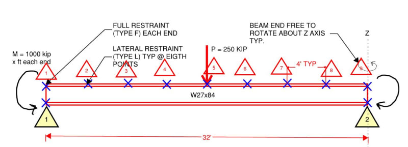
I'd also like for all parties to agree on the interpretation of the clause below.

THE CLAUSE IMPLIES THIS

When studying brace point #7, it is prudent to consider the absence of brace point #7 concurrently with the presence of brace points 1,2,3,4,5,6,8. It is this mental experiment that guides us to our determination with respect to which flange is critical and which flange moves the most in the absence of restraint.

THE CLAUSE DOES NOT IMPLY THIS

When studying brace point #7, it is prudent to consider the absence of brace points 2,3,4,5,6,7,8 (no restraint other than at the member ends).

THE POLL

Anybody disagree on this point?

c01_xb4r43.jpg

c02_tniymc.jpg
 
Human909 said:
Anyway I'll post my results both theoretical buckling and AS4100 calcs soon.

Do any of you Aussies have the calc set up as an easily modifiable spreadsheet, similar to what Celt83 has for AISC? If so, maybe we could tweak a few things quickly to figure out what the AS4100 method would look like if done KootK style. Beats waiting for Xmas if it's me doing it from scratch.
 
KootK said:
When studying brace point #7, it is prudent to consider the absence of brace point #7 concurrently with the presence of brace points 1,2,3,4,5,6,8. It is this mental experiment that guides us to our determination with respect to which flange is critical and which flange moves the most in the absence of restraint.

Rewrite

When studying brace point #7, it is prudent to consider the absence of brace point #7 concurrently with the presence of any brace points 1,2,3,4,5,6,8 located where the braced flange would be in compression. It is this mental experiment that guides us to our determination with respect to which flange is critical and which flange moves the most in the absence of restraint.

This sure does get complex. I was reading the doc below and, based on that, it sounds as though Trahair would have actually have preferred several methods even more complex that the current AS4100 one. I pitty the fool who finds himself a structural engineer in AU with English as a second language.

c01_orucob.jpg
 
Hey. KootK. I feel like I might be making a high school level mistake here but I'm getting your beam well into yielding without even considering buckling. My input. 9.75m long, 1112kN load, 1355kNm moment on end. Result ~387mPa peak stress...

KootK said:
I'd also like for all parties to agree on the interpretation of the clause below.
I think we all disagree with this clause as far as applying AS4100 is concerned. It isn't in line with how it is use or the spirit 5.5.2 and 5.5.3. That said logically your clause could be superior but it is impractical and is also potentially self referential. ie restrain 1 depends on restraint 2 and restraint 2 thus depends on restrain 1.


Here is the output:

AS4100 1998 CALCULATIONS FOR GROUP 1 (*=Failure)
------------------------------------

Critical load case is 1, out of 1

Section: *W27x84 (I or H section, Rolled/SR)

Failure Crit Start Finish Axial Major Minor Major Minor Load
Mode Case Pos'n Pos'n Force Shear Shear Moment Moment Factor

Section 1 0.000 0.00 0.00 556.03 -1355.82 0.00 0.66*
Member 1 0.000 2.438 0.00 -1355.82 0.00 0.66*
Shear 1 0.000 0.00 0.00 556.03 -1355.82 0.00 0.74*
(1.00)

Grade= 36 Fy = 248.2 MPa
Fyw = 248.2 MPa Fu = 399.9 MPa
Ltot = 9.754 m Lseg = 2.438 m (FL Bot-Top)
kt = 1.00 (5.6.3) kl = 1.00 (5.6.3)
kr = 1.00 (5.6.3) Le = 2.438 m (Bending) (5.6.3)
Lx = 9.754 m (Compression) Ly = 9.754 m (Compression)
Lz = 9.754 m (Torsion)
Ly/ry= 185.4 (Compression) Le/ry= 46.3 (Bending)

Arf = 0.0 mm^2 Arw = 0.0 mm^2
An = 15935.5 mm^2 Ae = 0.0 mm^2 (6.2.2)
Kf = 0.00 (6.2.2) Kt = 1.00 (7.3)
αm = 1.82 (5.6.1.1) αs = 0.93 (5.6.1.1)
αcx = 0.00 (6.3.3) αcy = 0.00 (6.3.3)
αb = 0.00 (6.3.3) βme = 0.00 (8.4.4.1)
βmx = 0.50 (8.4.2.2) βmy = 0.00 (8.4.2.2)
γ = 0.00 (8.3.4) ϕ = 0.90 (3.4)

N* = 0.00 kN
Vx* = 0.00 kN (not considered) Vy* = 556.03 kN
Mx* = -1355.82 kNm (Compact) My* = 0.00 kNm (Compact)

ϕNt = 0.00 kN (7.2) ϕNs = 0.00 kN (6.2)
ϕNcx = 0.00 kN (6.3.3) ϕNcy = 0.00 kN (6.3.3)
ϕNoz = 0.00 kN (8.4.4.1) ϕMo = 4476.96 kNm (5.6.1)
ϕVvm = 631.26 kN (5.12) ϕMf = 610.55 kNm (5.12.2)
ϕMsx = 893.21 kNm (5.2) ϕMsy = 116.41 kNm (5.2)
ϕMbx = 893.21 kNm (5.6) ϕMox = 0.00 kNm (8.4.4)
ϕMrx = 0.00 kNm (8.3.2) ϕMry = 0.00 kNm (8.3.3)
ϕMix = 0.00 kNm (8.4.2.2) ϕMiy = 0.00 kNm (8.4.2.2)
ϕMtx = 0.00 kNm (8.4.5.2) ϕMcx = 0.00 kNm (8.4.5.1)

Mx*
---- = 1.52 > 1.00* (Fail) Flexural-torsional buckling (5.6)
ϕMbx
 
Human909 said:
I feel like I might be making a high school level mistake here but I'm getting your beam well into yielding without even considering buckling.

That was by design (see my mathcad work in the problem statement). For modelling, I'd recommend either:

1) Jack up fy so it doesn't yield and accept a purely elastic buckling analysis or;

2) Keep the inelastic analysis and just report an ALR (applied load ratio) on a dummy applied load.

human909 said:
I think we all disagree with this clause as far as applying AS4100 is concerned.

Yeah, I was worried that might be the case.

Human909 said:
It isn't in line with how it is use or the spirit 5.5.2 and 5.5.3.

I'm not so sure. This might be yet another case where the wording is actually perfect in the literal sense. It's also partly why I was harping on the one stage vs two stage procedure previously. Done as separate checks for bottom chord and top chord buckling as we do in North America, it would go:

1) Study top chord buckling and cycle through each brace considering it removed with it's neighbors at compression location present.
2) Study bottom chord buckling and cycle through each brace considering it removed with it's neighbors at compression locations present.

Like anything else, judgement would eliminate 3/4 of the cases and it would go quickly. This would also be easy to program because it's methodical.

Human909 said:
but it is impractical and is also potentially self referential. ie restrain 1 depends on restraint 2 and restraint 2 thus depends on restrain 1.

I know, that's precisely why it concerns me.

Human909 said:
ϕMsx = 893.21 kNm (5.2) ϕMsy = 116.41 kNm (5.2)

So about 50% more capacity than AISC.

Human909 said:
kr = 1.00 (5.6.3) Le = 2.438 m (Bending) (5.6.3)

So 8' or 1/4 the the 32' that would be used via AISC.

Thanks for this. So much fun.


Kookt,
That was by design
Good to know I'm not going crazy.

So about 50% more capacity than AISC.
I get section capacity of 656 ft.kip vs 530ft.kip from Celt83. So 23% more capacity.
 
human909 said:
I get section capacity of 656 ft.kip vs 530ft.kip from Celt83. So 23% more capacity.

Ah yes.. I forgot to switch yours to kip-foot. Better. Thanks for the correction.
 
@Human909: Can you force your tool to run it at Le = 32' somehow? This would be how I would have done it if left to my own devices, pre-thread.
 
I gotta dissapear for a bit but here you go Kootk:
Le=32ft

AS4100 1998 CALCULATIONS FOR GROUP 1 (*=Failure)
------------------------------------

Critical load case is 1, out of 1

Section: *W27x84 (I or H section, Rolled/SR)

Failure Crit Start Finish Axial Major Minor Major Minor Load
Mode Case Pos'n Pos'n Force Shear Shear Moment Moment Factor

Section 1 0.000 0.00 0.00 556.03 -1355.82 0.00 0.66*
Member 1 0.000 9.754 0.00 -1355.82 0.00 0.38*
Shear 1 0.000 0.00 0.00 556.03 -1355.82 0.00 0.74*
(1.00)

Grade= 36 Fy = 248.2 MPa
Fyw = 248.2 MPa Fu = 399.9 MPa
Ltot = 9.754 m Lseg = 9.754 m (FF Bot-Bot)
kt = 1.00 (5.6.3) kl = 1.40 (5.6.3)
kr = 1.00 (5.6.3) Le = 9.754 m (Bending) (5.6.3)
Lx = 9.754 m (Compression) Ly = 9.754 m (Compression)
Lz = 9.754 m (Torsion)
Ly/ry= 185.4 (Compression) Le/ry= 185.4 (Bending)

Arf = 0.0 mm^2 Arw = 0.0 mm^2
An = 15935.5 mm^2 Ae = 0.0 mm^2 (6.2.2)
Kf = 0.00 (6.2.2) Kt = 1.00 (7.3)
αm = 1.70 (5.6.1.1) αs = 0.34 (5.6.1.1)
αcx = 0.00 (6.3.3) αcy = 0.00 (6.3.3)
αb = 0.00 (6.3.3) βme = -1.00 (8.4.4.1)
βmx = 0.50 (8.4.2.2) βmy = 0.00 (8.4.2.2)
γ = 0.00 (8.3.4) ϕ = 0.90 (3.4)

N* = 0.00 kN
Vx* = 0.00 kN (not considered) Vy* = 556.03 kN
Mx* = -1355.82 kNm (Compact) My* = 0.00 kNm (Compact)

ϕNt = 0.00 kN (7.2) ϕNs = 0.00 kN (6.2)
ϕNcx = 0.00 kN (6.3.3) ϕNcy = 0.00 kN (6.3.3)
ϕNoz = 0.00 kN (8.4.4.1) ϕMo = 378.60 kNm (5.6.1)
ϕVvm = 631.26 kN (5.12) ϕMf = 610.55 kNm (5.12.2)
ϕMsx = 893.21 kNm (5.2) ϕMsy = 116.41 kNm (5.2)
ϕMbx = 517.07 kNm (5.6) ϕMox = 0.00 kNm (8.4.4)
ϕMrx = 0.00 kNm (8.3.2) ϕMry = 0.00 kNm (8.3.3)
ϕMix = 0.00 kNm (8.4.2.2) ϕMiy = 0.00 kNm (8.4.2.2)
ϕMtx = 0.00 kNm (8.4.5.2) ϕMcx = 0.00 kNm (8.4.5.1)

Mx*
---- = 2.62 > 1.00* (Fail) Flexural-torsional buckling (5.6)
ϕMbx
 
Steveh49 said:
Is the AISC code routinely applied by checking different top and bottom flange unbraced lengths, eg full length of span for bottom flange as discussed in this topic?

I believe so, per Celt83's analysis.

Steveh49 said:
I wouldn't have read that from the Lb definition in F2.2. Seems pretty similar to AS/NZS: "braced against lateral displacement of the compression flange"
.

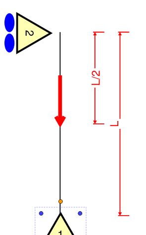
I see what you mean. Still, viewed from the perspective that I've been espousing, the bottom flange of any segment with an IP does qualify as a compression flange. And I believe that this is the North american dogma just as doing otherwise appears to be the AU dogma. A somewhat analogous situation is shown below. Would we call that something other than a compression column because the top half feels no compression? KL for that column is less than 1.0L but also greater than 0.5L.

c01_elmlhj.jpg
 
You could have at least chosen a Australian section and grade of steel if you wanted some software comparisons....
 
kootk said:

This is only important for your way of doing things, so how you apply it is up to you. Wasn't that the whole point of this exercise to see how you have interpreted the requirements? Trying to get us to agree is pointless as it's not how it's intended to be done.

 
Agent666 said:
You could have at least chosen a Australian section and grade of steel if you wanted some software comparisons....

What, I gotta post all the sketches, dig up all the articles, find the published examples, and craft the demo problems to suit other people's preferences? Fire up the ovaries and adapt something similar. We'll sort it out.
 
Agent666 said:
Wasn't that the whole point of this exercise to see how you have interpreted the requirements?

This is a somewhat separate aspect of the discussion that I'm hoping will yield interesting, additional discussion and possibly insight into the confusion over the critical flange definition. That said, it does of course tie into my general intent to try to understand the AS4100 LTB provisions.

Agent666 said:
This is only important for your way of doing things, so how you apply it is up to you.

Well yes, I do realize that I've got big boy pants on and can apply things as I like. I'm not seeking permission for that. Moreover, I don't do any real world AS4100 design. This is all just sport for me. Baby step by baby step, I'm trying to get us to consensus on the basics of the AS4100 provisions as a means to sussing out the root causes of our differences. This is one of those baby steps which is why it's important to me.

Agent666 said:
Trying to get us to agree is pointless as it's not how it's intended to be done.

Where can I sign up to be the arbiter of what is and is not worthwhile discussion? Seems like a good gig.

My impression here is that many of us, myself included, lack a cogent theoretical understanding of just how the AS4100 provisions work their magic. If we had such an understanding, I don't think that we'd be 160+ posts into trying to reconcile our differences on what should be entry level stuff. Instead, we'd just point to our cogent theoretical model and agree that "yup, it must be like this otherwise it wouldn't agree with the theory".

So I'm trying to construct such a cogent theoretical model and I was hoping that you and others would join me for that adventure. That said, it's not as though you're chained to this conversation like Prometheus to the stone. If you don't see any value in playing my reindeer games then don't play. Like a sack of bricks, you can just chose to put it down if you wish.

c02_th3qef.png
 
Well can I confirm a couple of things to get underway:-

The A36 material, is it actually 248.2MPa for both web and flange like human909's example implies (i.e. not different yield stresses for flange and web like many AU/NZ sections), only important for shear capacity I guess if there was shear and bending interaction.

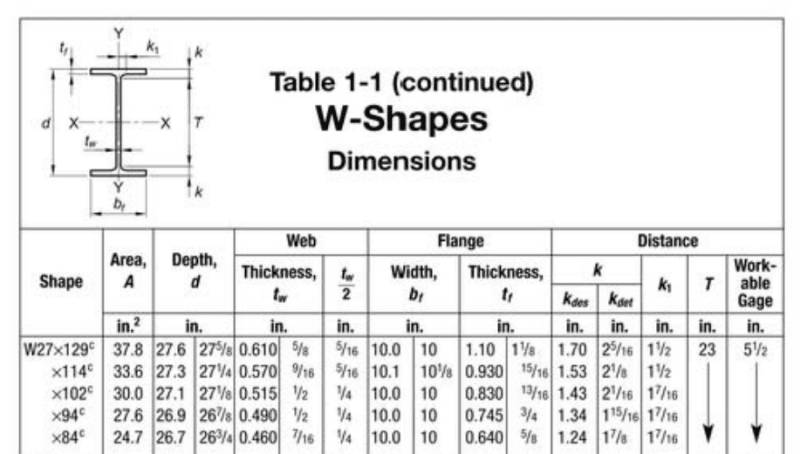
Whats up with the section dimensions of the W27x84? Me no understand given my ignorance with american sections?

The web is noted as 7/16" thick, then how is 1/2 the web thickness = 1/4"? Trying to work out root radius also results in no agreement between the k-t_f and k_1-t_w/2 dimensions. F#$%@%@g imperial rubbish? How are we supposed to work out section properties to AS/NZS standards without knowing the exact dimensions? Can someone please post this so we are working things out to the same dimensions.

Untitled_ylgxfy.png


Thanks
 
is the decimal value correct? as just noticed many don't equal the imperial fraction.....
 
Agent666, my fy value for steel is incorrect. Kootk I've updated the results. It changes the story a bit.

Here are the updated AS4100 calcs as per SpaceGass with higher strength steel

Le as per AS4100
AS4100 1998 CALCULATIONS FOR GROUP 1 (*=Failure)
------------------------------------

Critical load case is 1, out of 1

Section: *W27x84 (I or H section, Rolled/SR)

Failure Crit Start Finish Axial Major Minor Major Minor Load
Mode Case Pos'n Pos'n Force Shear Shear Moment Moment Factor

Section 1 0.000 0.00 0.00 556.03 -1355.82 0.00 0.91*
Member 1 0.000 2.438 0.00 -1355.82 0.00 0.91*
Shear 1 0.000 0.00 0.00 556.03 -1355.82 0.00 1.03
(1.00)

Grade= 50 Fy = 344.7 MPa
Fyw = 344.7 MPa Fu = 448.2 MPa
Ltot = 9.754 m Lseg = 2.438 m (FL Bot-Top)
kt = 1.00 (5.6.3) kl = 1.00 (5.6.3)
kr = 1.00 (5.6.3) Le = 2.438 m (Bending) (5.6.3)
Lx = 9.754 m (Compression) Ly = 9.754 m (Compression)
Lz = 9.754 m (Torsion)
Ly/ry= 185.4 (Compression) Le/ry= 46.3 (Bending)

Arf = 0.0 mm^2 Arw = 0.0 mm^2
An = 15935.5 mm^2 Ae = 0.0 mm^2 (6.2.2)
Kf = 0.00 (6.2.2) Kt = 1.00 (7.3)
αm = 1.82 (5.6.1.1) αs = 0.89 (5.6.1.1)
αcx = 0.00 (6.3.3) αcy = 0.00 (6.3.3)
αb = 0.00 (6.3.3) βme = 0.00 (8.4.4.1)
βmx = 0.50 (8.4.2.2) βmy = 0.00 (8.4.2.2)
γ = 0.00 (8.3.4) ϕ = 0.90 (3.4)

N* = 0.00 kN
Vx* = 0.00 kN (not considered) Vy* = 556.03 kN
Mx* = -1355.82 kNm (Compact) My* = 0.00 kNm (Compact)

ϕNt = 0.00 kN (7.2) ϕNs = 0.00 kN (6.2)
ϕNcx = 0.00 kN (6.3.3) ϕNcy = 0.00 kN (6.3.3)
ϕNoz = 0.00 kN (8.4.4.1) ϕMo = 4476.96 kNm (5.6.1)
ϕVvm = 876.75 kN (5.12) ϕMf = 847.98 kNm (5.12.2)
ϕMsx = 1240.57 kNm (5.2) ϕMsy = 161.68 kNm (5.2)
ϕMbx = 1240.57 kNm (5.6) ϕMox = 0.00 kNm (8.4.4)
ϕMrx = 0.00 kNm (8.3.2) ϕMry = 0.00 kNm (8.3.3)
ϕMix = 0.00 kNm (8.4.2.2) ϕMiy = 0.00 kNm (8.4.2.2)
ϕMtx = 0.00 kNm (8.4.5.2) ϕMcx = 0.00 kNm (8.4.5.1)

Mx*
---- = 1.09 > 1.00* (Fail) Flexural-torsional buckling (5.6)
ϕMbx

Le=L As per KootK
AS4100 1998 CALCULATIONS FOR GROUP 1 (*=Failure)
------------------------------------

Critical load case is 1, out of 1

Section: *W27x84 (I or H section, Rolled/SR)

Failure Crit Start Finish Axial Major Minor Major Minor Load
Mode Case Pos'n Pos'n Force Shear Shear Moment Moment Factor

Section 1 0.000 0.00 0.00 556.03 -1355.82 0.00 0.91*
Member 1 0.000 9.754 0.00 -1355.82 0.00 0.40*
Shear 1 0.000 0.00 0.00 556.03 -1355.82 0.00 1.03
(1.00)

Grade= 50 Fy = 344.7 MPa
Fyw = 344.7 MPa Fu = 448.2 MPa
Ltot = 9.754 m Lseg = 9.754 m (FF Bot-Bot)
kt = 1.00 (5.6.3) kl = 1.40 (5.6.3)
kr = 1.00 (5.6.3) Le = 9.754 m (Bending) (5.6.3)
Lx = 9.754 m (Compression) Ly = 9.754 m (Compression)
Lz = 9.754 m (Torsion)
Ly/ry= 185.4 (Compression) Le/ry= 185.4 (Bending)

Arf = 0.0 mm^2 Arw = 0.0 mm^2
An = 15935.5 mm^2 Ae = 0.0 mm^2 (6.2.2)
Kf = 0.00 (6.2.2) Kt = 1.00 (7.3)
αm = 1.70 (5.6.1.1) αs = 0.26 (5.6.1.1)
αcx = 0.00 (6.3.3) αcy = 0.00 (6.3.3)
αb = 0.00 (6.3.3) βme = -1.00 (8.4.4.1)
βmx = 0.50 (8.4.2.2) βmy = 0.00 (8.4.2.2)
γ = 0.00 (8.3.4) ϕ = 0.90 (3.4)

N* = 0.00 kN
Vx* = 0.00 kN (not considered) Vy* = 556.03 kN
Mx* = -1355.82 kNm (Compact) My* = 0.00 kNm (Compact)

ϕNt = 0.00 kN (7.2) ϕNs = 0.00 kN (6.2)
ϕNcx = 0.00 kN (6.3.3) ϕNcy = 0.00 kN (6.3.3)
ϕNoz = 0.00 kN (8.4.4.1) ϕMo = 378.60 kNm (5.6.1)
ϕVvm = 876.75 kN (5.12) ϕMf = 847.98 kNm (5.12.2)
ϕMsx = 1240.57 kNm (5.2) ϕMsy = 161.68 kNm (5.2)
ϕMbx = 543.63 kNm (5.6) ϕMox = 0.00 kNm (8.4.4)
ϕMrx = 0.00 kNm (8.3.2) ϕMry = 0.00 kNm (8.3.3)
ϕMix = 0.00 kNm (8.4.2.2) ϕMiy = 0.00 kNm (8.4.2.2)
ϕMtx = 0.00 kNm (8.4.5.2) ϕMcx = 0.00 kNm (8.4.5.1)

Mx*
---- = 2.49 > 1.00* (Fail) Flexural-torsional buckling (5.6)
ϕMbx
 
So according to your calc the beam has FLR which I'd expect as in it's a fairly large beam restrained to hell and back, its just the moment is higher than the section capacity so it was never going to work.

I'd probably take the next L restraint back from the IP just because it seems like you're assured it'll be to the compression flange which is the critical flange at this location. But I'd imagine the same or similar result given the moment gradient and resulting alpha_m and alpha_s product being easily greater than 1.0.

 
Status
Not open for further replies.

Part and Inventory Search

Sponsor