Continue to Site

Eng-Tips is the largest engineering community on the Internet

Intelligent Work Forums for Engineering Professionals

  • Congratulations KootK on being selected by the Eng-Tips community for having the most helpful posts in the forums last week. Way to Go!

Rafter without fly brace? 22

Status
Not open for further replies.

fourpm

Industrial
Oct 12, 2019
13
I am designing rafters to AS4100 and wondering what if I don't use fly brace. I understand that with fly brace it will give you full restraint. But if I don't use fly brace, will the purlin above be considered as lateral restraint for rafter under uplift? If so. can I take the purlin spacing as segment and the only factor that changes without fly brace is kt?
I have the same question when it comes the continuous steel floor beam design where Z/C floor joints sit on top of the beam. What segment should I take for the beam near the support? Can I take the floor joists spacing as segment with lateral restraint? Can anyone give me some examples? I have read some manuals but the examples they have are simply supported beams only. Thank you.
 
Replies continue below

Recommended for you

Human said:
The code allows you to perform buckling analysis OR follow the suggested guideslines. It doesn't suggest that the results will be identical.

Yes I’ve discussed that above, and mentioned reasons why it may be the case. See my post 9 Nov 19 22:30

Agent replied that I was simply misunderstanding it, and the two approaches should give the same answer when you view the problem correctly. Also, the code commentary refers to the compression flange guideline as a “more specific” version of the buckling check. That suggests it should give the same answer, which would agree with Agent.

But I tend to agree a compression flange need not deflect farthest. That assumption ascribes magical stabilising forces to the tension flange, similar in many ways to the idea that a tension flange cannot buckle, and that therefore an inflexion point alone can stabilise a beam.
 
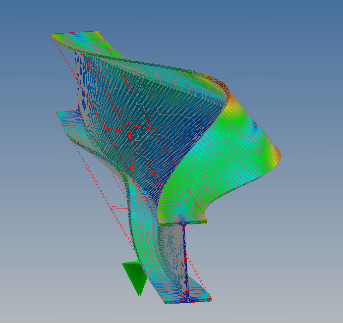
I've done some buckling analysis with Nastran In-Cad with various loading scenarios, simply supported and continuous. Top flange loaded and centre of beam loading. I've been getting the top flange buckling every time as the first buckling mode. I haven't really thought much was worth posting... AS4100 seems to be consevative by at least 50% for the scenarios being discussed on the particular model I chose. (8m long 250UB31)
250UB31_efqrb8.png


Of course you can always resort to LTB theory or simply run ask yourself which buckled shape has lower energy under gravitational load.
 
Interesting.

So you’re getting top flange moving most, even when top flange in tension?
 
Tomfh said:
Interesting.

So you’re getting top flange moving most, even when top flange in tension?
Buckling isn't only a compression phenomenon. It is better thought of as the system moving to a lower energy equilibrium. When the load is gravitational expect the buckling to result in lowering the potential energy of the load.

You can evern have tensile buckling on axial loading! (Though it is fairly contrived.)
 
Human, what type of analysis are you performing an elastic critical buckling analysis? And what is the loading and restrain conditions for the model picture you posted? You say you tried a whole lot of different things in the post but didn't make it clear what scenario you posted (just so we are all on the same page)?
 
Hey Agent. I've been performing linear buckling analysis. Non-linear is slower and seems to be virtually identical so I've stuck with linear for speed.
-Loading in the model picture was centre point load located central to the web. Fixed restraints at the end.

All the scenarios displayed similar top flange buckling as would be normally expected under gravitational load.
(Though you can get potentially get bottom flange bucking if you have no lateral or rotational at a support.)

Agent666 said:
You say you tried a whole lot of different things in the post but didn't make it clear what scenario you posted (just so we are all on the same page)?
Sorry for the lack of detail. I just posted the picture more as an example to people rather than evidence of anything. Like I have said nothing was surprising so there isn't much to post. But if you want a scenrio run I can do that. When I say nothing is surprising I mean it buckles as expected and as indicated by AS4100. When restraints are placed on a cross section of the critical flange the buckling load significantly increases.

Tomfh said:
I’m just trying to get some agreement here, as Agent as far as I can tell is saying compression flange has to buckle the furthest, ie the two checks are the same check...
{QUOTED FROM BELOW}
Fair enough. Sorry if I misunderstood. Yep tensions flange certainly buckle, cantilevers are a case in point.
 
Agent said:
Buckling isn't only a compression phenomenon. It is better thought of as the system moving to a lower energy equilibrium

Yea I know. The system takes the easiest path at every turn. At a certain point it’s easier for the beam to twist and kick out sideways than keep bending downwards....

I’m just trying to get some agreement here, as Agent as far as I can tell is saying compression flange has to buckle the furthest, ie the two checks are the same check...
 
Human,

If you have a chance could you do one with no lateral rotational restraint.
 
Sure. But you are going to have to be more specific. We need some rotational restrain otherwise it is unstable.
 
I mean without lateral rotational restraint at the supports. I.e. make the beam pin ended in plan. Currently it appears fully fixed against lateral rotation, ie the supports are providing very significant restraint to the lateral part of the buckle.
 
Does anyone have time to run a beam through Microstran/Space Gass code check. That would show how thousands of engineers are applying the code, consciously or not. I won't have access for a little while where I am.

Is the inflection point a particularly bad place for a brace? Re Yura's 10% increase in capacity. Would a brace to the compression flange (AS/NZS terminology: only one flange braced) further along the beam be more effective?

How do you all visualise which flange will move further without computer analysis?

 
Is the AISC code routinely applied by checking different top and bottom flange unbraced lengths, eg full length of span for bottom flange as discussed in this topic? I wouldn't have read that from the Lb definition in F2.2. Seems pretty similar to AS/NZS: "braced against lateral displacement of the compression flange".

I did see the Yura article posted by KootK summarised in the commentary but it's not clear to me that it has been brought into the code itself.
 
steveh49 said:
Does anyone have time to run a beam through Microstran/Space Gass code check. That would show how thousands of engineers are applying the code, consciously or not. I won't have access for a little while where I am.
Yep. I've tested it on SpaceGass as requested. It applies the codes as I believe is literally written. Specifically when it comes to lateral restraints:

5.4.2.4 Laterally restrained
A cross-section of a segment whose ends are fully or partially restrained may be considered
to be laterally restrained when the restraint effectively prevents lateral deflection of the
critical flange (see Clause 5.5) but is ineffective in preventing twist rotation of the section,
as for example in Figure 5.4.2.4.


EG A fixed end an beam of length L with a single load in the middle will with restraints on the top flange at 24% and 76% of L will have an effective length bending length of L. Whereas the same beam with restraints at 26% and 74% will have segments of effective lenth of 0.26L, 0.48L and 0.26L. The effect of the restraint is determined whether the flange is critical, aka in compression.

This is to code but is quite perverse.

steveh49 said:
Is the inflection point a particularly bad place for a brace? Re Yura's 10% increase in capacity. Would a brace to the compression flange (AS/NZS terminology: only one flange braced) further along the beam be more effective?
If we are talking about the code then yes. If we are talking about reality it can get complicated but I would say braces close to the load is more effective.

steveh49 said:
How do you all visualise which flange will move further without computer analysis?
You load is being pulled by gravity. Imagine the buckling shape that will lower the lower (reduce the potential energy).

Tomfh said:
I mean without lateral rotational restraint at the supports. I.e. make the beam pin ended in plan. Currently it appears fully fixed against lateral rotation, ie the supports are providing very significant restraint to the lateral part of the buckle.
No matter how you spin it. With a single span you still have top flange buckling. There is no scenario that I'm aware of where the bottom flange buckles that reduces the potential energy.
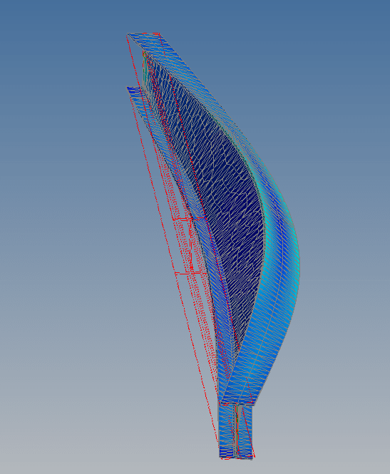
Anyway here you go...
temp_ufn7uu.png
 
Thanks very much to everyone who supplied links to additional examples following my last post. Good stuff.

Tomfh said:
They’re all like that.

Gotcha. I feel compelled to voice a minor grievance here however. If similar examples abound, it sure would have been nice if somebody had posted one rather than letting me spin for 5000 posts until I dug one up myself.

Agent666 said:
I haven't looked at it too hard, but I gather from the replies from others that it supports our side of the conversation

Indeed it does, at least from the "how does everybody in AU apply this" perspective. As I mentioned, in my last post, this raises unanswered theoretical questions for me about the method itself. More that more later though.

Tomfh said:
..and there must be some authority who understands it correctly, and who simply must agree with you.

I never said this, you're putting words into my mouth. I thought that it would be rational, and productive, to seek out some published examples to help support one perspective or the other. So I took the initiative and did that.
 
Tomfh said:
You have this idea that everyone’s misinterpreting it..

Not everyone, just you and Agent. And I feel that was a rational approach. In the interest of dialing down the antagonism and defensiveness that plagues this thread, perhaps there would be benefit in my explaining my approach to this debate so far. If nobody cares... feel no pressure to read further. This will be off topic.

Having spotted something that I fundamentally disagreed with at the beginning of the thread, I saw the possible outcomes here being as follows, listed from most probable to least probable:

1) KootK is wrong. Most likely.
2) Tomfh and Agent are wrong. In between likely.
3) All of Australia is wrong. Least likely (mass delusion that I referred to earlier).

It would have been very convenient to just stop at #1 given that my being incorrect is the most likely outcome here. But, then, this thread would be five posts long instead of 75 posts long. And all of the value that we've jointly created here simply would not exist. And I would neither learn nor grow. So I chose to take #1 off of the table and assume that I was correct until someone (possibly myself) was able to convince me otherwise. I simply don't know how to conduct a debate without first assuming that I hold a valid opinion.

Next, I moved on to #2, given that I feel that is the second most likely outcome. Surely Tomfh and Agent being wrong is more probable than all of Australia being wrong. So I challenged your interpretations. Similar to #1, I simply don't know how to prosecute a debate where nobody challenges anybody on anything. Obviously, challenging people on things inevitably ruffles some feathers. While I can't control how others perceive my challenges, I can assure everyone that I mean no disrespect -- and minimal hostility -- when I issue them.

Lastly, I proceed to the least likely outcome which is that all of Australia is wrong about lateral torsional buckling. Now that I consider possibility #2 sufficiently vetted and eliminated, this is where I'm at. At present, I now do disagree with AS4100 on a theoretical level. That said, I still acknowledge that the most likely outcome here is #1: I'm wrong and/or simply lack understanding somewhere.
 
Tomfh said:
Failing that, working towards getting some resolution I suggest we provide a detailed design on a beam and loading scanerio, kootk then does a counter design using his interpretation so we can appreciate exactly how he's going about applying the provisions.

I like this idea. However:

1) Before I start, I'd like to agree on the best example. I'm thinking either OP's original one or the manual example that I posted.

2) I'd like someone to run the example via software first and then provide me with a meaningful beam size and loading to check.

3) It's quite likely that I wont get to this until Xmas break. From now until Dec 31, I'm stuck in PDH Armageddon.
 
Choose your poison via an appropriate sketch (beam geometry, loading scenario, restraint locations, etc so it demonstrates whatever differences you are looking for with regard to the reversal of moment/inflection point), I'll choose some random magnitude of load and size an appropriate beam. Also I believe I said that not Tomfh.

It'll be interesting as well if you can compare to aisc or equivalent to see if any fundamental differences in capacity come out of it at the end of the day.
 
Human909 said:
Could you please give an example where the (mis)interpretation results in overestimating LTB capacity?

Human909 said:
This one's easy. The original OP example where I say the unbraced length is the length between supports and Agent666 says that it would be a value less than that.

Human said:
However I crunch the numbers using buckling analysis software I get greater movements on the top flange. I also get higher buckling resistance with the top flange laterally restrained. Ignoring top lateral restrains seems unnecessarily conservative.

For this, I submit that you're using incorrect assumptions. The "next in line" buckling mode for the beam under consideration is section rotation about the intersection of the web and top flange. So there should be no lateral movement of the top flange to consider. And yes, the lateral restraints to the top flange do improve capacity. That's what changes the buckling mode from:

1) Rotation about a point in space above the shear center and, in all likelihood, well above the beam to;

2) Rotation about the point in space where the web intersects the top flanges, sometimes termed constrained axis buckling.

With this in mind, the key difference between my method and Agent's would be:

3) I feel that the unbraced length should be the beam span between supports.

4) Agent feels that the unbraced length should be, roughly, the distance from the supports to the inflection points (my interpretation of his position). It's easier to talk about this if we just assume that top flange restraint is effectively continuous. I'm not accusing Agent of doing IP bracing here.

Obviously, one would think that these two different interpretations would lead to a large discrepancy in capacity. One of my hopes with this thread is that I'll be able to parse out just why that isn't the case (assuming that it isn't). Viewing AS4100 from my North American perspective, I find it odd that one seems to be able to evaluate a flange buckling mode using unbraced compression flange buckling lengths that wind up being less than the distance between points of compression flange lateral restraint. My guess is that it's "baked into the cake" of the method someplace but I just haven't discovered where yet.

Interestingly, the wording of AS4100 implies the conversion of segment length into "effective length" via some factors. One idea I've been exploring is whether or not that effective length ends up being something close to what I would consider the "real" unbraced length when all is said and done. Unfortunately, in playing with it, I've so far been unable to demonstrate that equivalency to myself.
 
kootk said:
Interestingly, the wording of AS4100 implies the conversion of segment length into "effective length" via some factors. One idea I've been exploring is whether or not that effective length ends up being something close to what I would consider the "real" unbraced length when all is said and done. Unfortunately, in playing with it, I've so far been unable to demonstrate that equivalency to myself.

In most cases where the load is laterally restrained, constrained to be acting through the shear center (k_t=1.0), then the length will either be slightly higher through the k_l factor, or quite a bit lower using the k_r factor.

If one segment in a member achieves full lateral restraint (this is basically meaning it has enough restraint to achieve the plastic moment capacity), then the adjacent segment can take one end being restrained against minor axis rotation in plan (can take k_r =0.85 for adjacent segment for example). If segments on both ends of segment have FLR, then you can take k_r=0.7 for that segments design. You can achieve the same effect through rigidly connecting to intersection members if they are stiff enough.

If you took k_r=0.7, which requires an F or P restraint at each end. Then the curve I posted comparing to AISC, results in much less difference between the two standards. This may suggests AISC maybe assumes this inherently, whereas we have to prove it. But as I noted previously the American curve is more of an average through experimental results, whereas the NZ/AU one is definitely more of a lower bound as I understand it.
 
Status
Not open for further replies.

Part and Inventory Search

Sponsor