Continue to Site

Eng-Tips is the largest engineering community on the Internet

Intelligent Work Forums for Engineering Professionals

  • Congratulations KootK on being selected by the Eng-Tips community for having the most helpful posts in the forums last week. Way to Go!

Rafter without fly brace? 22

Status
Not open for further replies.

fourpm

Industrial
Oct 12, 2019
13
I am designing rafters to AS4100 and wondering what if I don't use fly brace. I understand that with fly brace it will give you full restraint. But if I don't use fly brace, will the purlin above be considered as lateral restraint for rafter under uplift? If so. can I take the purlin spacing as segment and the only factor that changes without fly brace is kt?
I have the same question when it comes the continuous steel floor beam design where Z/C floor joints sit on top of the beam. What segment should I take for the beam near the support? Can I take the floor joists spacing as segment with lateral restraint? Can anyone give me some examples? I have read some manuals but the examples they have are simply supported beams only. Thank you.
 
Replies continue below

Recommended for you

kootk said:
I find it odd that one seems to be able to evaluate a flange buckling mode using unbraced compression flange buckling lengths that wind up being less than the distance between points of compression flange lateral restraint

If you have L restraints, you cannot get the effective length lower than the physical length between L restraints. It's either going to be the same length or higher through the k_l or k_t factors. k_r = 1.0 as soon as an L restraint is present.
 
kootk said:
If you have L restraints, you cannot get the effective length lower than the physical length between L restraints. It's either going to be the same length or higher through the k_l or k_t factors. k_r = 1.0 as soon as an L restraint is present.

I understand and have been interpreting it the same. But I still observe the same oddity. In my world, and Yura's, the buckling length is between points of F-restraint only. If K_this and K_that get it back to the same place, then peachy, concern alleviated. I'm not yet convinced that's the case.
 
Agent666 said:
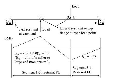
Choose your poison via an appropriate sketch (beam geometry, loading scenario, restraint locations, etc so it demonstrates whatever differences you are looking for with regard to the reversal of moment/inflection point)

Yesss... now where getting somewhere.

I chose the example shown below. I'd like you to arrange the span, load, and beam size to make the example as meaningful as possible. My thoughts in that regard:

A) A slender-ish beam rather than a stocky one to exacerbate LTB issues.

B) Loads producing something in the range of 125% over load for checking bottom flange buckling LTB in segment 1-3.

I'm also going to add some rules to the game:

KootK said:
1) Before I start, I'd like to agree on the best example. I'm thinking either OP's original one or the manual example that I posted.

2) I'd like someone to run the example via software first and then provide me with a meaningful beam size and loading to check.

3) It's quite likely that I wont get to this until Xmas break. From now until Dec 31, I'm stuck in PDH Armageddon.

4) I expect somebody to pony up with an FEM investigation when the time is right. Part of my reasoning in choosing this example is that I feel it will FEM better in the absence of true continuity.

5) I'm going to probe AS4100 theory more deeply here before I dive in. I expect some real cooperation with that rather than defensive xenophobia.

c01_bqwhn3.jpg
 
KootK said:
For this, I submit that you're using incorrect assumptions. The "next in line" buckling mode for the beam under consideration is section rotation about the intersection of the web and top flange. So there should be no lateral movement of the top flange to consider. And yes, the lateral restraints to the top flange do improve capacity. That's what changes the buckling mode from:

1) Rotation about a point in space above the shear center and, in all likelihood, well above the beam to;

2) Rotation about the point in space where the web intersects the top flanges, sometimes termed constrained axis buckling.

Just an FYI. I looked at multimodes and still didn't see the buckling mode you described. I ran a large variety of gravitational load cases with different restrains, different load heights and included some continuous beams. The only time I ever got significant movement of the bottom flange was bottom supported unrestrained at the support. (Which isn't surprising if you view the support as an upwards load.) I haven't posted all this because nothing I found was particularly noteworthy.

KootK said:
Hold off on the example. I can do better
Great. I'll run it both with buckling analysis and to AS4100 as implimented by SpaceGass.

Oh and Kootk. Good to have you back, I hope the inlaws was fun! :) You contribution is helpful, anything that makes people think about things is good. Your understanding of LTB is no doubt better than mine. Bit I too will debate and question stuff that doesn't quite look right. As far as AS4100 goes, it does seem a little screwy in its binary determination of 'the critical flange' which leads to perverse results as I noted earlier. So far I haven't seen anything unconservative in it's treatment of LTB but the simplifications do make it excessively conservative in some scenarios.
 
Steve said:
13 Nov 19 11:27
Does anyone have time to run a beam through Microstran/Space Gass code check.

Microstran counts lateral restraint on compression flange as an L restraint, which it uses to define effective length. It does it according to code.
 
Agent said:
There is no scenario that I'm aware of where the bottom flange buckles that reduces the potential energy.


Thank you for doing the laterally unrestrained case.

I’m sure I’ve seen buckling cases where bottom flange buckles more. The bottom flange of a continuous beam carries a lot of compressive strain energy, which can be shed via a lateral buckle (a point KootK is emphasising).Maybe they’re just obscure cases that don’t matter..


In any case, you results confirm the point of the critical flange not necessarily being the compression flange, as you show top flange buckling the most, even when it’s in tension.
 
It will be the Cb vs alpha,m difference that saves the day. Yura's Cb numbers for beams with inflection points are much larger than alpha,m from the A/NZ codes, moreso if you shorten the segment with intermediate lateral restraints.

I'm not sure about the potential energy definition. Isn't that equivalent to requiring the centre of rotation be below the beam, otherwise rotation will lift the beam? What about beams in space?
 
Tomfh said:
I’m sure I’ve seen buckling cases where bottom flange buckles more. The bottom flange of a continuous beam carries a lot of compressive strain energy, which can be shed via a lateral buckle (a point KootK is emphasising).Maybe they’re just obscure cases that don’t matter.
You are correct my statement is not completely accurate. There are some cases where you see exactly what you describe. But at least for my chosen example and combinations this occurs well beyond yield points and well beyond other less obscure buckling cases.

Previously I was focussing on unrestrained flange cases as that is what we were discussing. KootK mention "constrained axis buckling" so that is what I modelled just now.

temp_g4cxwm.png

But bear in mind that occurs at ~10x the load of the unconstrained case and about ~10x beyond the yield point.
 
Human909 said:
Just an FYI. I looked at multimodes and still didn't see the buckling mode you described.

I'm not surprised. As I mentioned somewhere above, I think that it would take a pretty contrived example to make OP's real world situation go south. But I'm going to do my darnedest to contrive just such an example. We. Shall. See.

There's something about my world view here on Eng-Tips that I've been hesitant to share because it's difficult to articulate without my sounding like a raging egomaniac. I have something important in common with Albert Einstein. I know, right? Sadly, that thing is neither intelligence nor creativity. Rather, what we have in common is that we both consider the mental experiment to be the source of all understanding.

Almost everything that Einstein came up with was the byproduct of a a handful of mental experiments that required no laboratory work to develop. Yes, experiments were later done by others for verification and that was in important step. But Einstein didn't let the eventual need for such verification hold him back from dreaming the big dreams.

When I come at something hard here on Eng-Tips, I go straight for the root, physical theory of it and pursue that like a dog with a bone in a way that, frankly, some find off putting. I run my own mental experiments until I feel that I've gotten the model perfected in my head. For me, this is the way that I learn and discover. The flip side of this coin is that:

1) While I respect that FEM results have value, that's never sufficient for me.

2) While I respect that code interpretations have value, that's never sufficient for me.

3) While I respect that empirical testing has value, that's never sufficient for me.

4) While I respect that gobs of analytical data have value, that's never sufficient for me.

5) I tend scoff at homework assignments asking me to provide code interpretations, empirical data, analytical date, or FEM results. I just don't care all that much about these things compared to the root, physical model in my head.

So I guess that's my roundabout way of saying that I'm not overly concerned about whether or not your FEM model predicts the buckling mode that I described. If it can be predicted on paper, and in the model in my head, that's what interests me. I would actually argue thatt he buckling mode that I described is the only logical "next in line" mode regardless of whether it's "far off" or not. And I've got a hunch that this far-off-ness might be used to resolve the apparent discrepancy between "compression flange" and "flange that moves most". More on that later.

KootK said:
Oh and Kootk. Good to have you back, I hope the inlaws was fun!

Thanks, it's good to be back. I actually had to put this down not because of time constraints (doesn't take much) but because I was getting too distracted thinking about this to be "present" with my family. Found myself zoning out on conversations with people that I haven't seen in three years. Not good.
 
Steve49 said:
I'm not sure about the potential energy definition. Isn't that equivalent to requiring the centre of rotation be below the beam, otherwise rotation will lift the beam? What about beams in space?

I don't think so. All roads lead back to the load making it's way closer to the earth. What it does mean, however, is:

1) It gets really, really hard to make something buckle via the constrained axis buckling model where the bottom flange swings upwards.

2) Sometimes you'll get a secondary peak/trough in the stability graph. While one might argue that intermediate point might not be reliably stable, it sure does make it a lot less likely that you'll see real failures in the real world. And interesting, and quite related example of this is tension chord buckling in trusses.
 
KootK said:
Rather, what we have in common is that we both consider the mental experiment to be the source of all understanding.
I hear you. Mental models and asking the right questions can take you an extremely long way.

KootK said:
So I guess that's my roundabout way of saying that I'm not overly concerned about whether or not your FEM model predicts the buckling mode that I described. If it can be predicted on paper, and in the model in my head, that's what interests me.
I totally get that.

The FEM analysis is a tool. It could readily be wrong or just not have the right inputs. As I showed above I did force the buckling mode out of the closet with the restraints you mentioned and plenty of load.

Steve49 said:
I'm not sure about the potential energy definition. Isn't that equivalent to requiring the centre of rotation be below the beam, otherwise rotation will lift the beam? What about beams in space?
Beams in space still have a potential energy given by the load direction. Gravity on a mass is just the convenient and most common supplier of the force. An alternative could be a pnematic cyclinder where the potential energy is the compressed gas, any movement in the cylinder deflecting/buckling a beam is a reduction in that potential energy. Plenty of structural analysis can be done in terms energy conservation. In basic deflection the load supplies work and the beam strain energy in the beam is equal to that work.
 
Human said:
Previously I was focussing on unrestrained flange cases as that is what we were discussing.

Agree. The unrestrained case is the relevant one for this discussion, as that defines the critical flange for a new lateral restraint, e.g. a midspan restraint.

When I said bottom flange can buckle I meant in the unrestrained case. Not higher order buckling modes. If it only happens in higher order buckling modes then it can be ignored.

HUman said:
As I showed above I did force the buckling mode out of the closet with the restraints you mentioned and plenty of load.

Did you restrain only top flange? I would have thought you'd see a half wave buckle of the bottom flange. That's what kootk is concerned about.
 
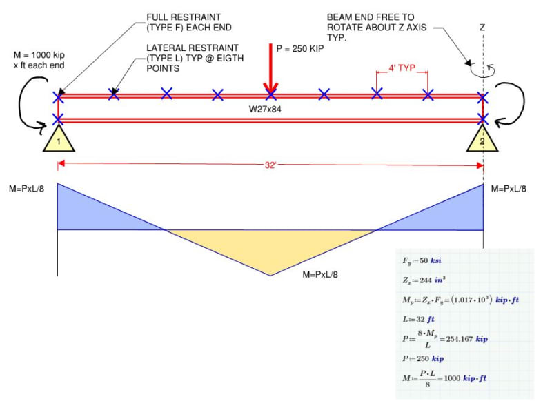
Revised, proposed test case attached and shown below. Closer to OP's case and should do more to exacerbate effective length discrepancies.

c01_hp1p6a.jpg
 
think that 24 ft in your diagram should be 32 ft

Edit:
I know you all are focused on the AS4100 and I'm interested to see the various results after reading all of the above.

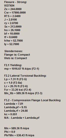
As some one that was taught AISC's method this is how I learned to check KootK's above example:
Lb for postive moment = 4 ft < Lp = 7.31 ft determined via equation F2-5 -> Lp = 1.76 ry sqrt(E/Fy)
LTB not applicable for this case
Mp = Zx Fy = 1016.67 ft-kips equation F2-1

Lb for negative moment = 32 ft > than both Lp and Lr -> LTB must be checked
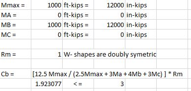
Calculation for Cb:
Capture_ruwlww.jpg


Calculation of Yielding, LTB, and Compression Flange Local Buckling:
Capture_suqzpf.jpg


Open Source Structural Applications:
 
Tomfh said:
That's what kootk is concerned about.

It should be what everybody is concerned about.

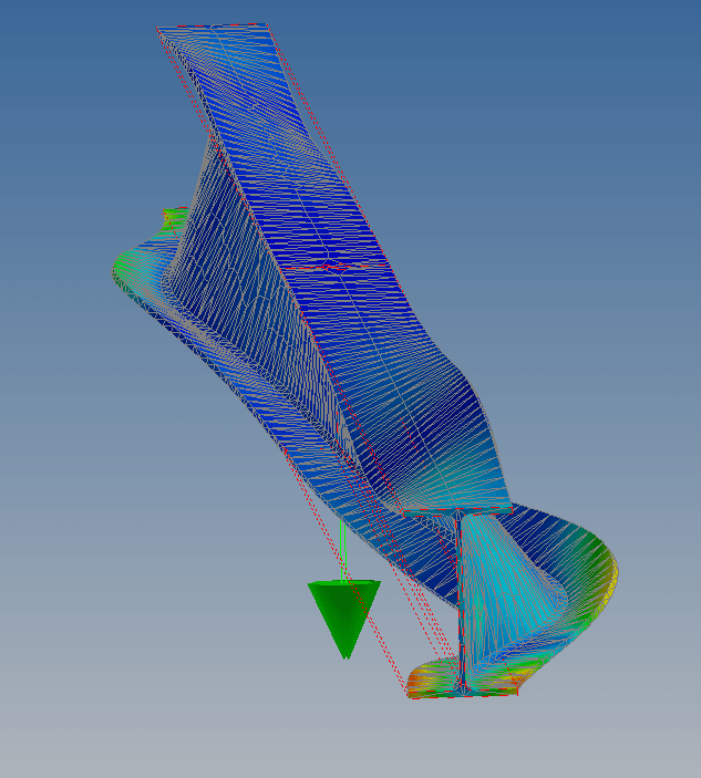
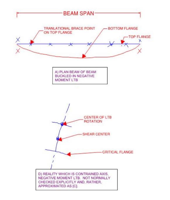
As I see it, the buckling mode shown below is the only practical LTB buckling mode worthy of consideration here. OP didn't tell us the joist spacing but I presume it's close enough that the top flange can be thought to be continuously braced.

Does anybody disagree that the LTB buckling mode shown below is "the thing" as far as this discussion goes? We're wasting our time on the rest if we don't all first agree on this.

c02_vcwywy.jpg
 
Tomfh said:
Did you restrain only top flange?
Yes.

Tomfh said:
I would have thought you'd see a half wave buckle of the bottom flange. That's what kootk is concerned about.
I've never seen this in my modelling and I've tried hard to make it happen. (short of imposing loads upwards) It also doesn't make sense to me as a possibility because a full wave would mean an increase in height of the loaded points on the beam. Which goes against energy conservation. (If the beam buckles you must have a weighted net movement of the load on the beam in the direction of the load, otherwise conservation of energy is violated!)

Celt83 said:
I know you all are focused on the AS4100 and I'm interested to see the various results after reading all of the above.
Other codes for comparison are just as important. Thanks.

Kootk said:
It should be what everybody is concerned about.

As I see it, the buckling mode shown below is the only practical LTB buckling mode worthy of consideration here. OP didn't tell us the joist spacing but I presume it's close enough that the top flange can be thought to be continuously braced.

Does anybody disagree that the LTB buckling mode shown below is "the thing" as far as this discussion goes? We're wasting our time on the rest if we don't all first agree on this.
From my perspective the conversation long moved away from the example you posted because we spent a while discussing and analysing the UNRESTRAINED case. If we are talking about continually restrained top flanges then that is an entirely different scenario. The effective length according to AS4100 is heavily reduced as previously discussed. To reiterate we get 3 segments with their effective length the distance from the restraint to the inflection point, inflectio to inflection and inflection to restraint.

The inflection point isn't a restraint, but it is where the restrainst become effective if you follow AS4100.
SpaceGass and Microstran implement it this way.
 
celt83 said:
think that 24 ft in your diagram should be 32 ft

Correct. Gratitude.

celt83 said:
I know you all are focused on the AS4100 and I'm interested to see the various results after reading all of the above.

1) I was intending to do this anyhow so you've saved me some effort.

2) This serves as a nice check that the example makes sense and produces the result that I was intending.

3) Acknowledging that I'm surely bypassing a lot of nuance, it seems to me that the AS4100 effective length would need to be about 400% of the segment length for equivalency.

4) I would have calculated this as you have. That said, it's prudent to acknowledge that this method is not the constrained axis method which would yield a higher capacity. This is what I was alluding to in the statement below from long, long ago. This is yet another thing that I'm starting to wonder about. Perhaps the AS4100 method does actually account for the contrained axis effect in a way that the stock AISC procedure does not.

KootK said:
6) As shown in sketch D below, our real world expectation is actually constrained axis buckling about the top of the beam. This usually has a higher capacity than sketch C but is a serious pain the the butt to calculate so we just go with sketch C and call that good enough.
 
Human909 said:
Which goes against energy conservation. (If the beam buckles you must have a weighted net movement of the load on the beam in the direction of the load, otherwise conservation of energy is violated!)

I disagree. Anything that rolls the beam on its side and results in deflection tend towards the Iy value rather than the Ix satisfies the energy conservation. That said, these points are germane to this. The effect of the top flange rotating and initially raising the joists would be an example of the secondary peak/trough business.

KootK said:
1) It gets really, really hard to make something buckle via the constrained axis buckling model where the bottom flange swings upwards.

2) Sometimes you'll get a secondary peak/trough in the stability graph. While one might argue that intermediate point might not be reliably stable, it sure does make it a lot less likely that you'll see real failures in the real world. And interesting, and quite related example of this is tension chord buckling in trusses.
 
Human said:

Ok, fair enough.

Human said:
It also doesn't make sense to me as a possibility because a full wave would mean an increase in height of the loaded points on the beam. Which goes against energy conservation. (If the beam buckles you must have a weighted net movement of the load on the beam in the direction of the load, otherwise conservation of energy is violated!)

Yeah, you may be right that the load helps stabilise the bottom flange. I need to think more about that...

Where are you loading these examples?
 
Status
Not open for further replies.

Part and Inventory Search

Sponsor