Continue to Site

Eng-Tips is the largest engineering community on the Internet

Intelligent Work Forums for Engineering Professionals

  • Congratulations KootK on being selected by the Eng-Tips community for having the most helpful posts in the forums last week. Way to Go!

Rafter without fly brace? 22

Status
Not open for further replies.

fourpm

Industrial
Oct 12, 2019
13
I am designing rafters to AS4100 and wondering what if I don't use fly brace. I understand that with fly brace it will give you full restraint. But if I don't use fly brace, will the purlin above be considered as lateral restraint for rafter under uplift? If so. can I take the purlin spacing as segment and the only factor that changes without fly brace is kt?
I have the same question when it comes the continuous steel floor beam design where Z/C floor joints sit on top of the beam. What segment should I take for the beam near the support? Can I take the floor joists spacing as segment with lateral restraint? Can anyone give me some examples? I have read some manuals but the examples they have are simply supported beams only. Thank you.
 
Replies continue below

Recommended for you

Perhaps the example that I posted can serve as a focal point for us to iron out some misunderstandings. Something a little more tangible too pick apart.

Tomfh said:
That example contradicts everything you’ve been saying.

That's interesting because, in my opinion, it contradicts absolutely nothing that I've been saying. Can you point to a specific example or three that I can attempt to speak to?

In the morning, I'll:

1) Try to demonstrate how the example contradicts what you and Agent666 have been saying.

2) Address Human909's request that I contrast the example to Agents666's statements.

Human909 said:
Could you please give an example where the (mis)interpretation results in overestimating LTB capacity?

This one's easy. The original OP example where I say the unbraced length is the length between supports and Agent666 says that it would be a value less than that.

Human909 said:
His 'interpretation' does not seem to contradict mine.

I'm not clear on what your interpretation actually is Human909. Did you state that someplace? Can you reproduce or restate it here?

It's 9pm in Canadia and my inlaws are in town. That's all I've got in the tank for tonight.

 
Tomfh said:
No, because kootk has been arguing from the start that you cannot count L restraints to reduce your effective length.

This needs greater precision to represent my position. KootK argues that:

1) You absolutely CAN count top flange L restraints for checking LTB represented by rotation about a point in space below the shear center.

2) You cannot count top flange L restraints for checking LTB represented by rotation about a point in space above the shear center, particularly one located at the intersection between the beam web and beam top flange.

KootK said:
Do you guys do a similar, bifurcated check where negative bending LTB and positive bending LTB are checked separately? Or do you tackle it in a single checking procedure?

I asked this question of Tomfh and Agent666 long ago and received no response. Can one or both of answer this simple question for me now? It's complicated but I've got a hunch that this may be important in getting this sorted. For reference, this is what I mean by a bifurcated checking procedure:

KootK said:
1) I think that it's critical to recognize that, with moment reversal, the design effort has to bifurcate into two paths:

a) LTB rotation about a point in space below the shear center which is used for the positive moment / top flange check (sketch B below).

b) LTB rotation about a point in space above the shear center which is used for the negative moment / bottom flange check (sketch C below).


kootk said:
Can you point to a specific example or three that I can attempt to speak to?

...


Kootk said:
3) use the beam span between supports (8m) as your effective, lateral torsional buckling length for the negative moment.

Kootk said:
I say the unbraced length is the length between supports

In these examples there are lateral restraints attached to the compression flanges. According to AS4100 that counts as an L restraint, which reduces your segment length. You do NOT need to take the full length between fully restrained supports as your segment length.

It’s not a matter of “interpretation”, it’s what the code says, it’s what the writers meant, and it’s been part of Australian design logic for 50 years at least.
 
KootK said:
It's 9pm in Canadia and my inlaws are in town. That's all I've got in the tank for tonight.
Well thanks for contributing. [smile]

KootK said:
I'm not clear on what your interpretation actually is Human909. Did you state that someplace? Can you reproduce or restate it here?
I haven't really stated it. I've been a bit non comittal and probably even inconsistent. (sorry, its a bit weak) I've read your posts with interest, agreed with some things. I do agree that 4100 could be clearer. But I don't believe that Agent666's interpretation devitates from the intention. I don't have a clear view on the whole discussion which is why I am interested.

KootK said:
"Could you please give an example where the (mis)interpretation results in overestimating LTB capacity?" This one's easy. The original OP example where I say the unbraced length is the length between supports and Agent666 says that it would be a value less than that.
Thanks. I'm going crunch the numbers using buckling analysis and see what I come out with....

KootK said:
Do you guys do a similar, bifurcated check where negative bending LTB and positive bending LTB are checked separately? Or do you tackle it in a single checking procedure?
It is tackled in the single checking proceduce and supposably sufficiently caputured by the defintions of segment lengths and critical flange restraints. It does seem to be a simplification, but is it unconservative? I'll try to let the computer crunch the numbers and get back to you.
 
KootK said:
That example contradicts everything you’ve been saying.

Nope, turns out your were absolutely right about that. I mistakenly thought that there was F-restraint at 3. So now I'm utterly confused by the manual statement that the bottom flange will buckle between 1 & 3 when every bone in my body tells me that makes no physical sense. With no bottom flange restraint between supports, I just don't see it doing the voodoo that I've shown in the sketch below. I am however starting see how the AS4100 dogma has made the rounds.

Do you have any additional published examples of LTB on beams with inflection points? This one is the sum total of what I can find in my stuff.

c01_fuqfv3.png
 
Human909 said:
It is tackled in the single checking proceduce and supposably sufficiently caputured by the defintions of segment lengths and critical flange restraints. It does seem to be a simplification, but is it unconservative?

Yeah, I was worried that it would turn out to be a single procedure. That is a significant difference and points to something being fundamentally different in the treatment that doesn't yet make sense to me. I don't know how to cover both top flange and bottom flange LTB in a single check without getting into fancy computer stuff.

Is there a definitive, very theoretical steel text that folks refer to in Australia? Something like Salmon & Johnson in the US? Both of the Aussie book that I've got are pretty lightweight in their treatment of LTB, including the Trahair one unfortunately. They're most just cookbook, how you do stuff manuals.
 
Kootk said:
Do you have any additional published examples of LTB on beams with inflection points?

They’re all like that.

It’s how it’s done.

You have this idea that everyone’s misinterpreting it and there must be some authority who understands it correctly, and who simply must agree with you.

Forget that. We don’t do it your way.
 
There are a few worked examples from ASI and standards Australia and lecture notes that I'm aware of, but they just reinforce what Tomfh is saying and what I've said previously and the example that kootk provided (I haven't looked at it too hard, but I gather from the replies from others that it supports our side of the conversation).

I'll fish them out so we can either settle it or go another round.
 
Failing that, working towards getting some resolution I suggest we provide a detailed design on a beam and loading scanerio, kootk then does a counter design using his interpretation so we can appreciate exactly how he's going about applying the provisions.
 
Agent,

Can you respond to my comment 10 Nov 19 00:42.

I’d like to get to the bottom of this “buckles the furthest” thing. If I’m misunderstanding it I’d like to know.

Still struggling to understand how the compression flange can be considered to always buckle the furthest, even at cross sections where the tension flange buckles the most.
 
I'll try tomorrow, but in the interim I and others want to know what situation you are interpreting the tension flange as wanting to buckle the furthest at a point of restraint?
 
Kookt said:
Yeah, I was worried that it would turn out to be a single procedure. That is a significant difference and points to something being fundamentally different in the treatment that doesn't yet make sense to me. I don't know how to cover both top flange and bottom flange LTB in a single check without getting into fancy computer stuff.
I recognise and agree with you concern that AS4100 does seem to take a few simplifying shortcuts. Though I've yet to determine how conservative or unconservative they are. I'm working on a variety of scenarios and putting some comparisons together compared to buckling analysis. Bare in my I am pretty ignorant of other codes and pretty ignorant of deeper LTB theory. But I figure this is a good approach to become less ignorant.

Kookt said:
Is there a definitive, very theoretical steel text that folks refer to in Australia? Something like Salmon & Johnson in the US? Both of the Aussie book that I've got are pretty lightweight in their treatment of LTB, including the Trahair one unfortunately. They're most just cookbook, how you do stuff manuals.
I've only seen lightweight. Most of the teaching that I've seen is pretty light weight too (prosciptive follow the code stuff).
 
Kootk said:
This one's easy. The original OP example where I say the unbraced length is the length between supports and Agent666 says that it would be a value less than that.
However I crunch the numbers using buckling analysis software I get greater movements on the top flange. I also get higher buckling resistance with the top flange laterally restrained. Ignoring top lateral restrains seems unnecessarily conservative.

Tomfh said:
I’d like to get to the bottom of this “buckles the furthest” thing. If I’m misunderstanding it I’d like to know.

Still struggling to understand how the compression flange can be considered to always buckle the furthest, even at cross sections where the tension flange buckles the most.
It isn't being considered like that. In the code you have two choices, perform an elastic buckling analysis to determine which flange will buckle the furthest. OR the choices given which manages to cover most scenerios with closely enough.
 
Human said:
In the code you have two choices

I know. I keep saying as much.

The point is you can get two different answers for a given cross section - eg. top flange critical based on compression flange check, vs bottom flange critical via an elastic buckling check.

Human said:
However I crunch the numbers using buckling analysis software I get greater movements on the top flange

This is interesting. What software are you using? What sort of beam setup? How are you restraining the beam?


Agent666 said:
There are a few worked examples from ASI
Do you mean this?

Please do fish out section 5.12 if you have it. I inherited an older version (1990ish) from a retiring engineer, scanned it, threw out the paper and now find I've lost the scan. Very disappointed in myself. Found it online so I can live with myself again. The comment at the end of example 5.8 might actually be more relevant to how the AS buckling gurus (Trahair & Bradford, not sure who Bridge is) meant the code to be applied. But it's late and I haven't thought it through - attached for discussion.


I haven't read the whole thread in detail yet (only opened it based on the number of replies) but it seems the two viewpoints may have an order of magnitude difference in final capacity based on the difference in effective length being discussed, unless something compensates along the way of the calculation. That would mean failures left, right & centre which of course we don't experience.
 
That was one of the examples I was thinking of that demonstrates the application of the code requirements. Will find more tonight.

The other references I thought of are HB48 (I think) by standards Australia, simplified design of steel members by SESOC, probably a multitude of publications by HERA and SCNZ as well.
 
Is a fly brace anything like a rat run?

Mike McCann, PE, SE (WA, HI)


Agent said:
but in the interim I and others want to know what situation you are interpreting the tension flange as wanting to buckle the furthest at a point of restraint?

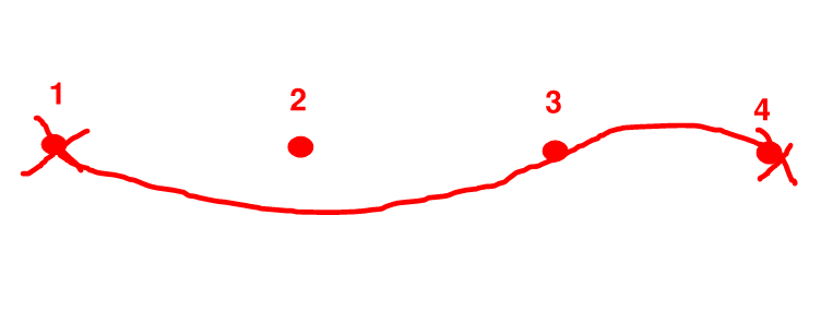
The continuous beam scenario. Continuous beam with full restraint each end, but no lateral restraints.

Look at kootks post on 17 Oct 19 22:56. like that with no lateral restraints. Just F restraints at the supports.

The bottom flange has varying stresses, ranging from compression at the ends, to tension in the middle.

The top flange has the opposite stresses.

I think the bottom flange will deflect further at every cross section when the beam buckles. Even where the bottom flange is in tension.

On the other hand human is saying his buckling runs show the opposite, and always show the top flange buckling more (which in itself would contracdict the compression flange always being critical, since much of the top flange is in tension).

And you're saying I'm completely misunderstanding it because you need to take the cross section in isolation.

So I'm not really sure what to make of it..

 
Tomfh said:
The point is you can get two different answers for a given cross section - eg. top flange critical based on compression flange check, vs bottom flange critical via an elastic buckling check.
Yep. And there where is the problem with that. The code allows you to perform buckling analysis OR follow the suggested guideslines. It doesn't suggest that the results will be identical.
 
I'd need to do a buckling analysis, but I'd tend to agree with human on expecting the compression flange at any particular cross section being the one that deflected the furthest.

Edit - never seen the effect you're noting to be fair, it's always the compression flange moving further at any cross section unless you're dealing with cantilevers.
 
Status
Not open for further replies.

Part and Inventory Search

Sponsor