steveh49 said:
Not sure if I've had an epiphany about what KootK wants to understand about AS4100 or whether he'll turn around and say this is obvious and everyone already knows, but here goes.
I would think that the silver bullet here would almost
have to be something that is obvious to some parties and opaque to others.
steveh49 said:
For AS4100, an L restraint is as good as an F restraint except that you can't use k_r < 1.0 with L restraints.
Yes, if L-restraints are as good or nearly as good as F restraints then this would be a epiphany from my end. It would explain the anomaly, from my perspective, that is AS4100 treating the buckling length as something near to the subsegement lengths (8' here) when the actual, physical length of the LTB phenomenon is the entire beam length (32' here). This will have two dimensions for me:
1) Verifying that this is how AS4100 works and;
2) Justifying that this approach is theoretically appropriate.
Phase two can wait. For now, just having phase one settled would be a massive win for me in the understanding department.
Massive. And I see your point, the graph below would suggest that, at least in some situations, An L-brace might be considered effectively an F-brace.
steveh49 said:
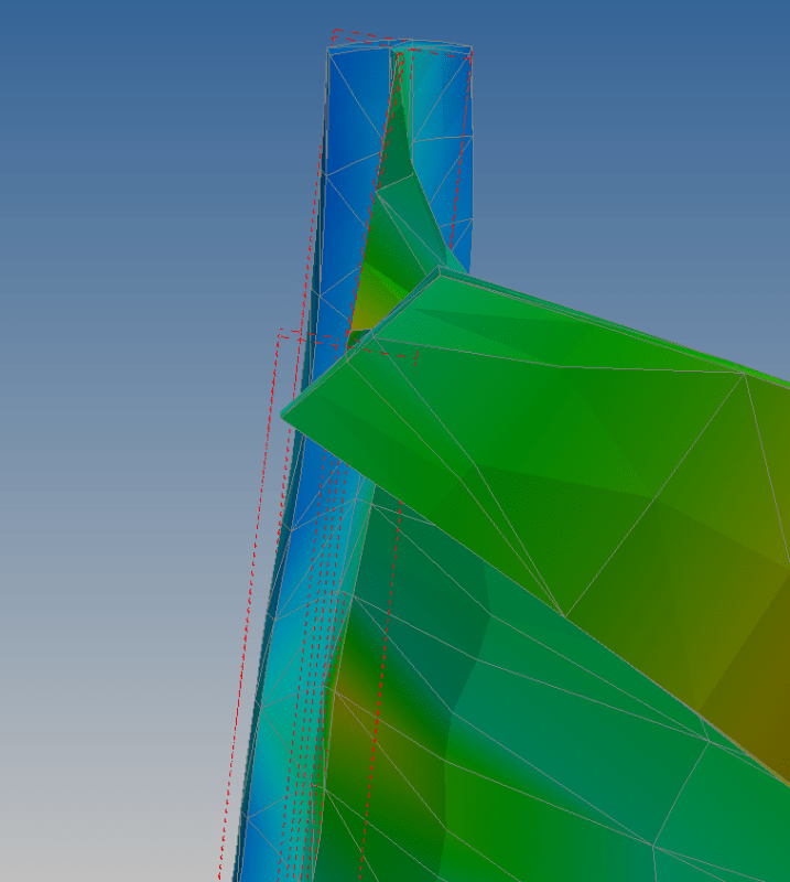
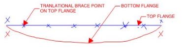
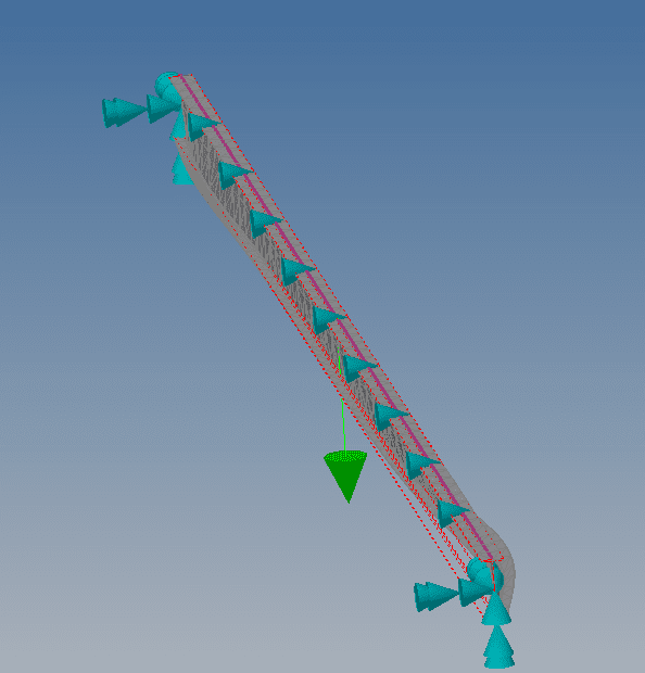
I find human909's latest buckling shape image interesting as it appears to match the AS4100 assumption: the bottom flange is only moving near the beam ends where it is in compression and the top flange restraints are ineffective at restraining the bottom flange. It looks straight and along its original alignment in the middle of the beam where it is in tension. The top flange L restraints are acting as F restraints. But this is very different to the Mastan buckled shapes and key to the AS4100 'magic' being correct for moment reversal within segment.
Mastan and Human909's stuff are both just FEM models. One way or another, they have to be made to agree. In my mind, the differences between software models cannot stand as the "key" to explaining the AS4100 magic. Three things about Human909's model catch my eye and, hopefully, he can speak to them:
1) If I understand the symbology correctly, there is still some degree of weak axis rotational restraint at the beam ends.
2) The bottom flanges buckle in
opposite directions. That S-shape suggests that this is something other than first mode behavior. This may be related to my next point.
3) Graphically, it appears that the load may have been applied at a point lower on the cross section than the top flange.