Continue to Site

Eng-Tips is the largest engineering community on the Internet

Intelligent Work Forums for Engineering Professionals

  • Congratulations KootK on being selected by the Eng-Tips community for having the most helpful posts in the forums last week. Way to Go!

Rafter without fly brace? 22

Status
Not open for further replies.

fourpm

Industrial
Oct 12, 2019
13
I am designing rafters to AS4100 and wondering what if I don't use fly brace. I understand that with fly brace it will give you full restraint. But if I don't use fly brace, will the purlin above be considered as lateral restraint for rafter under uplift? If so. can I take the purlin spacing as segment and the only factor that changes without fly brace is kt?
I have the same question when it comes the continuous steel floor beam design where Z/C floor joints sit on top of the beam. What segment should I take for the beam near the support? Can I take the floor joists spacing as segment with lateral restraint? Can anyone give me some examples? I have read some manuals but the examples they have are simply supported beams only. Thank you.
 
Replies continue below

Recommended for you

I'll add my thanks to everyone on this topic. I tried to catch up on stars that I definitely owe but have hit the limit and the forum is robbing Peter's posts to give a star to Paul at this stage. Odd.

I need to re-read the all-encompassing theory but what's the verdict with moment reversal and L restraints? On first reading, if it's about flange buckling like a column, it seems that both flanges need to be braced similar to AISC method. Have I got that right?

Here's the paper I was pulling graphs from. Light on theory as it was mainly meant to enable design by buckling analysis without doing a buckling analysis but may be of interest and perhaps even useful in real designs.


KootK said:
my antipodean frenemies
I notice no-one else lasted the distance. Are we really that obnoxious?

Thanks very much for doing those Mastan cases. I will get around to doing with them what I wanted to. In one case that's on the proviso that I remember what I was trying to prove. This thread has moved pretty fast.
 
Agent666 said:
Kootk, aren't you actually comparing the As4100 capacity to AISC capacity to a elastic critical buckling moment though? They are two different things and not comparable in any way. I've said it a few times now in the thread but if I'm reading it right people don't understand me or something? The mastan2 buckling moment is not the design capacity.

I see what you're saying and are mostly correct. However, let's clarify a few things:
For discussion sake I think of capacity as the final design including a reduction factor. I don't think any of us are talking about this. I think we should stick with "nominal" capacities or "nominal" strengths. So no reduction or factor of safeties.

Next. (speaking in terms of AISC here) The overall capacity of the member will depend on which limit state governs. So if (according to AISC) you are in the elastic LTB length you could check LTB with a hand equation and compare this to your Mastan2 model. You could use either of these results for your elastic buckling nominal capacity. (Hopefully I have this all correct).
What I don't know is how well of a job we have done comparing these to AS4100. Meaning that is the Mb number (see quote below) the nominal strength of the beam considering all limit states? Or Just a buckling limit state. If the procedure is more of an envelope procedure, than I'm curious to know what the final nominal capacity is (hoping that it is less than elastic buckling found in Mastan2).
Kootk said:
Mb = 1171 k-ft = AS4100 LTB number assuming a segment length of 8'. This exceeds Mp of course.

Agent666 said:
But I am seeing the same differences in capacity, in my checks on the 70 ft case with L restraints only in the 5/8, 4/8, 5/8 span locations as per code requirement for consideration. The end span is critical. The difference from the hand check over 8001mm segment gives ~phiMbx = 682kNm. But the capacity from a buckling analysis method is coming out at phiMbx = 269kNm. This is just using table 5.6.1 case 1 for calculating alpha_m (have not calculated alpha_m using 5.6.4(b) method to see if that would be different).

Could you maybe expand on this from your side when you get a chance. I have a hard time following where these numbers come from.

So the end span hand check (this is done using AS4100) for unbraced length of 8001mm (26.25ft) gives nominal capacity of 682kNm (503kip*ft)
However your check of the elastic buckling gives a moment of 269kNm (198.4kip*ft)
- How did you check elastic buckling?

In your eyes do you see this as AS4100 being unconservative or are you saying that there might be other code provisions which would reduce your nominal strength?

Thanks for staying with this.


EIT
 
Those are the final design capacities, this the only thing that's important for comparing results. I'll put up a full calc in due course to illustrate my methodology though so it can be reviwed/critiqued. The problem is everyone's quoting numbers but I'm not even sure what they are half the time, capacities getting mixed up with buckling moments and so forth.

I'm not even sure people are using their analysis tools correctly, we've got mastan models with no warping turned on, FEM models that are/were giving rubbish results, etc. Then making conclusions based on these results.

Regarding design by buckling analysis, I'm just following the code requirements for this (CL 5.6.4). Taking reference buckling moment M_o from the buckling analysis instead of from the equation, and getting significant differences once you back calculate out the moment modification factor alpha_m. I don't think anyone else is doing this from what I can see, but are still comparing apples with oranges. Happy to be corrected on this, which is why I raised it for clarification to make sure we are all talking the same language.

I suspect if you use the buckling moment value from the buckling analysis for determining F_e in AISC, you'll see the same disagreement probably when compared to the hand method (I'll try compare this as well, but I'm no AISC expert). I haven't seen anyone that I recall, using the buckling analyses to follow through and compare both AISC method for another comparison point to see if that agrees better when AS4100 doesn't seem to.

All I'm saying is you do it by hand using the normal 'hand check' provisions by basically following the prescribed effective length method and get more than twice the design capacity you get by following the buckling analysis route through to a design capacity which is actually working out the theoretical effective length based on your scenario of member/support/restraint/loading. As others have noted, this should be something we should probably concentrate on.
 
RFreund, AS4100/NZS3404 do the elastic/inelastic thing all in one step/equation as a reduction/scaling factor. Comparison curves have been posted previously comparing the two methods for the exact same member conditions.
 
Agent666 said:
When I check your file to see what everyone is going on about regarding the apparent unconservatism (because I haven't really been following along with tht line of the conversation), I note the model doesn't have warping set to continuous. So results are not quite valid as you get a reasonable benefit from this.

You are right about the warping continuity issue in the second 70' example. Thanks for catching that.

I have verified that warping continuity was turned on in all of the 32' examples that I ran so those should stand as originally posted in that regard.

Here's how the 70' example changes with the warping continuity issue corrected.

- Applied Load Ratio = 0.1026 0.13034
- Fails at 0.1026 0.13034 x 250k = 26k 33k point load
- Fails at 2768 kip*in 3421 kip*in end moment = 313 kN*m 387 kN*m (25% 31% of your phi.Ms. value of 1240 kNm)


The updated Mastan file is attached.
 
 https://files.engineering.com/getfile.aspx?folder=62b12da5-5a07-475b-9a0a-85d44d72cd3d&file=ETW27x8403.mat
Agent666 said:
The problem is everyone's quoting numbers but I'm not even sure what they are half the time, capacities getting mixed up with buckling moments and so forth.

If the no imperfections buckling moment is less than AS4100 standard method predicts then it’s already unconservative, isn’t it?
 
Agent666 said:
Can you confirm you are doing this please when comparing these numbers?

Not confirmed. I am most definitely not doing that.

KootK said:
Mastan elastic critical buckling, sans imperfections

Agent666 said:
I'll say it again, you don't need imperfections modeled when doing the eigenvalue analysis (elastic critical load analysis in mastan2).

I realize that imperfections don't need to be modeled to run an eigenvalue analysis. However, the results of an eigenvalue will not reflect the decrease in capacity resulting from imperfections if those imperfections are not given explicit consideration in the buckling analysis model. It was this latter point that I meant to convey. I'm trying to ensure that anyone reading the results does't erroneously assume that some consideration has been given to imperfection in my Mastan runs when it has not.

Agent666 said:
Kootk, aren't you actually comparing the As4100 capacity to AISC capacity to a elastic critical buckling moment though?

Absolutely, and that is by design.

Agent666 said:
They are two different things and not comparable in any way. I've said it a few times now in the thread but if I'm reading it right people don't understand me or something? The mastan2 buckling moment is not the design capacity.

I thought that'd I'd already explained this...

Agent666 said:
You all need to stop quoting the reference buckling moment directly as a capacity, it isn't!

KootK said:
"You all" is a pretty big bucket. Does it include my work? It shouldn't. Two perfectly valid things can be done with the reference buckling moments from FEM:

1) Compare one reference buckling moment to another so suss out the impacts of various changes to the situation.

2) Use a reference buckling moment as an upper bound capacity.

I believe that I carefully placed all of my stuff into one of those two buckets with statements like the one below that I included along with my modelling results.

I believe that valid comparisons can be made and I am confused by your assertions to the contrary. I think that one just has to understand the nature of what is being compared. So I'll just tell you what I had in mind in greater detail and you can let me know what parts you object to:

1) For both AISC and AS4100, I take the adjusted LTB values coming out of Mastan as upper bounds to the true capacity. As far as I know, any subsequent adjustment factor such as phi_b or alpha_s only serve to lower the capacities generated by Mastan.

2) I take both the AISC and AS4100 design capacities calculated the traditional way as lower bound capacities.

3) If I find that the upper bound capacities coming out of Mastan (#1) are lower than the lower bound capacities coming out of AISC/AS4100, then I conclude that there's a problem that needs sorting (tomfh's last point I think).

4) I don't worry about converting the raw Mastan values to code appropriate, buckling analysis design values because any such conversion is only going lower the Mastan capacities and exacerbate any problems discovered in step #3). What was a problem at #3 just becomes more of a problem.

Are these not valid comparisons to make?

For an AISC audience, things work out great as AISC doesn't consider imperfections for LTB and the Mastan values are effectively [Mn] as far as I know. This is perfect for comparison.

For an AS4100 audience, I believe that I'm effectively providing [Mb/alpha_s]. Clearly, further post-processing isn't required to identify the discrepancies that currently concern us but, if anyone would like to undertake such post-processing, they are welcome to.

 
RFreund said:
If the procedure is more of an envelope procedure...

As far as I'm concerned, we have established that the procedure is most definitely not an envelope procedure in the sense that this has been proposed previously. With the arrival of the Trahair doc provided by steveh49, it became clear that:

1) AS4100 is assuming L-braced points to be effectively braced against cross-section rotation for certain situations.

2) AS4100 is in fact evaluating particular, individual buckling modes, one for each segment between the L-braces thought to be equivalent to F-braces.

3) The only curve fitting going on is the micro-kind similar to what we do with Cb in the AISC methodology.

We've seen the wizard behind the curtain now and the magic is not what what it was purported to be.

@RFreund: I'm not trying to beat you up on this. I just want all parties here to be clear that we've moved on from the enveloped family of curves business. That, or I'd like to hear about any lingering doubt that may exist on the matter.
 
Agent666 said:
Edit, just to clarify for multiple segments you need to follow 5.6.4 procedure, and evaluate on a segment by segment basis still for critical limiting segment

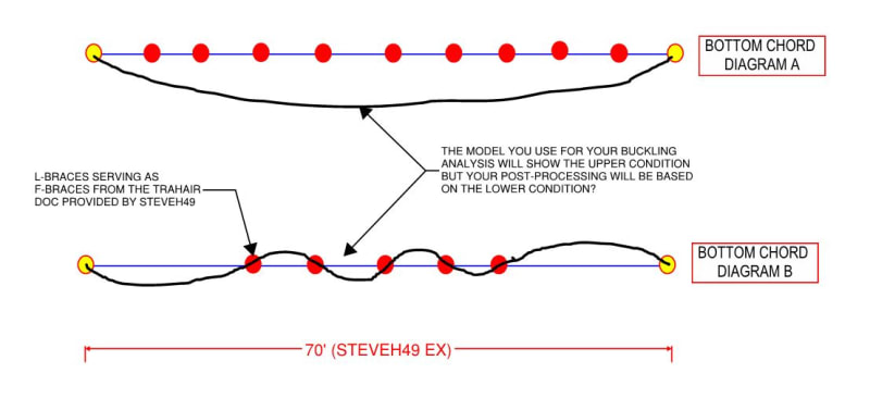
Hold the phone... are you saying that, using the buckling analysis option, you'd still do the AS4100 post-processing segmentally? Even though your FEM model would show you something completely different (sketch below)? I had not anticipated that and it strikes me as a terribly inconsistent mix-match of the stories being told. Consider the following as it would pertain to the 70' beam example:

1) Your FEM shows buckling as a single half sine wave. Your post processing assumes six half sine waves.

2) Your FEM has provided you with information about a single buckling mode and you are applying it to six different cases, none of which match the FEM.

3) I would think that your slenderness parameter would be badly overestimated by segmental treatment and would be much more appropriately calculated based on the 70' beam length.

How do you rationalize this?

c06_uadwsy.jpg
 
RFreund said:
Also in the same breath though, I'm reminded of the number of structures that I've seen with continuous beams and no stiffeners/braces at columns and have not had issues (yet?).

The failure shown below happened in my neck of the woods and was judged to be the result of missing beam/column joint stiffeners allowing web side sway buckling to take place: Link.

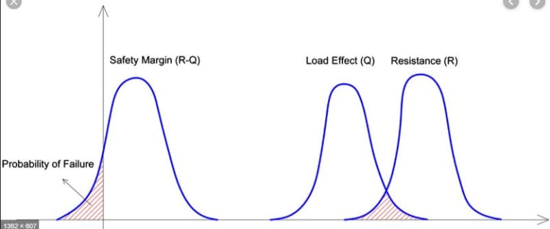
The graph below is largely responsible for why failures don't happen and has two important, negative consequences for us:

1) it makes it difficult for structural engineers to demonstrate their value to society and;

2) it makes it difficult to separate luck from skill / correctness over the horizon of any one man's life span.

c05_boybnu.jpg


Structural_Reliability_Chart_dtgxpq.jpg
 
steveh49 said:
I need to re-read the all-encompassing theory but what's the verdict with moment reversal and L restraints? On first reading, if it's about flange buckling like a column, it seems that both flanges need to be braced similar to AISC method. Have I got that right?

I've certainly not arrived at a hard verdict yet and will reserve judgment until I've had a few days to review the latest article that you've kindly provided. I do have an interesting observation regarding two flange bracing and AISC though.

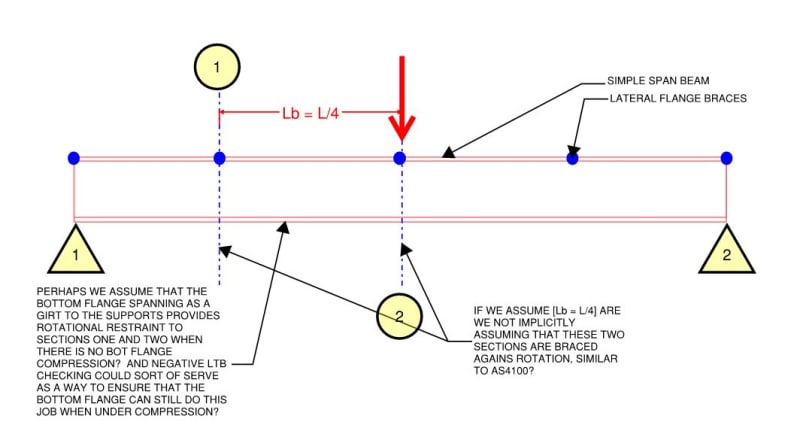
As you know, I've oft been quoting Yura's thing where he appears to suggest that the unbraced LTB length be the length between points of zero twist. I thought of an example where this recommendation is not followed however: pretty much every simple span beam ever (sketch below/attached). What to do...

c01_y87rde.jpg


c01_kn826o.jpg
 
kootk said:
Absolutely, and that is by design.

I don't see a problem with this. That's essentially what you do when using the elastic buckling method version (except you also factor down the buckling load slightly via alpha S because obviously you can't use the idealised buckling load for a real beam).

kootk said:
Hold the phone... are you saying that, using the buckling analysis option, you'd still do the AS4100 post-processing segmentally?

My understanding of the buckling method is it sidesteps all that. You don't calculate segment lengths, effective lengths, etc. You are essentially just calculate the buckling load, factoring it via alphaS, and use that directly. The alphaM factor drops out.

Kootk said:
We've seen the wizard behind the curtain now and the magic is not what what it was purported to be.

I'm not ready to conclude that just yet, but things are not looking as good as they did :(

Hopefully these buckling models are wrong somehow, and hopefully there's a deeper rationale for counting L's as F's generally.


Kootk said:
pretty much every simple span beam ever (sketch below/attached). What to do...

I think in the simple span case the bottom flange doesn't move at the position of the L restraint, thus increasing restraint level to F by bracing the bottom flange is redundant in those instances, and thus you can treat them as equivalent. That seems to be a large part of the basis for AS4100 saying L's are F's are equivalent.

Maybe you could run some mastan analyses with simple span with top L restraints and see if you can get the bottom (non critical) flange moving?
 
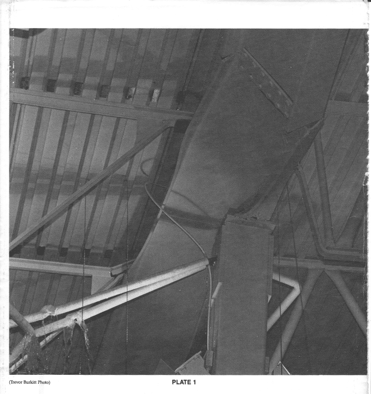
Below is Plate 1 from the Station Square Report by Dan Closkey. It shows the configuration of the cantilevered beam after failure but before collapse. The joists would normally be considered lateral supports for the beam, but the dark rectangle at the underside of one joist shoe suggests to me that the welding of that joist may have been omitted.

Plate_1_ksu9wg.png


BA
 
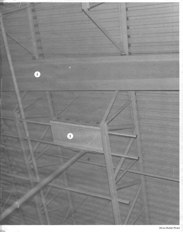
This is a photo of the drop-in span after failure of the cantilevered beam. The darkened rectangle under each joist shoe suggests that these two joists were not welded to the beam. If so, the lack of lateral bracing of the top flange of both the cantilever and supported beam could have been a contributing factor in the collapse.

Scan_20191126_4_bq2va5.png


BA
 
Tomfh said:
Maybe you could run some mastan analyses with simple span with top L restraints and see if you can get the bottom (non critical) flange moving?

Right. I somehow already managed to forget that I have the power to explore this stuff on my own.

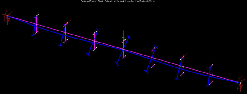
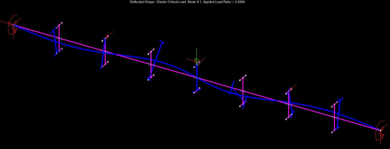
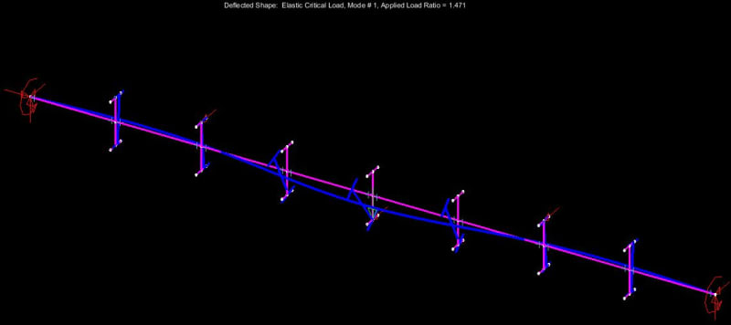
All three runs are the same W27x84, 32' beam with L-restraint at the first and third quarter points.

CASE 1. ALR = 0.65 which is actually less than the negative bending on our test case (0.69). Gobs of section rotation at the 1/4 point L-restraints. This case has a concentrated load at mid-span without lateral restraint at the point of loading. This would be a rare occurrence in practice but might be something to bear in mind at, say, a beam transferring a column from above. Makes the default practice of a stiffener pair under the column seem quite prudent.

CASE 2. Point load at top flange and accompanied by lateral restraint. A little section rotation at the 1/4 point L-restraints. ALR = 3. Not worth thinking about.

CASE 3. Point load at bottom flange accompanied by lateral restraint there. ALR = 1.5. Next to no section rotation at the 1/4 point bracing. Normal positive bending LTB check with the unbraced length equal to 0.5L would pick this up perfectly so not an issue.

CONCLUSION: tough to find a practical situation where cross section rotation at an L-brace would be in issue for a simple span beam.

c01_bveey3.jpg

c02_gqfuzk.jpg

c03_hwppzx.jpg
 
Kootk said:
CONCLUSION: tough to find a practical situation where cross section rotation at an L-brace would be in issue for a simple span beam.

Makes sense. Not a lot of strain energy to shed from the bottom flange.

I do hope AS4100 isn't extrapolating the simple case where L is effectively equivalent to F, and applying it to all cases.

 
I think that the biggest takeway from this thread is probably this: when time permits, everybody should download their free copy of Mastan and learn to tinker. It's just too much fun. Plus, in all future stability threads, we'll be able to pedantic, nearly unassailable egomaniacs at our leisure. That right there's worth the price of admission.
 
Kootk's Reference said:
A design approach that is consistent with current design provisions is to define the unbraced length as the spacing between points of zero twist...
Is this in AISC? Or where is the this from?
I've always understood that you can either restrain the compression flange from lateral movement or prevent twist. Which in the fixed end beam the bottom flange is only braced against lateral movement at supports.

Also is there somewhere I can 'borrow' AS4100?

EIT
 
Kootk said:
everybody should download their free copy of Mastan and learn to tinker

Definitely. I’m going to get it. I’m learning a lot seeing all these test cases.

What I’d love to see is some real buckling results of continuous beams, with real L restraints. That would help settle it.

I wonder if there’s published results easily available?
 
Status
Not open for further replies.

Part and Inventory Search

Sponsor