Continue to Site

Eng-Tips is the largest engineering community on the Internet

Intelligent Work Forums for Engineering Professionals

  • Congratulations KootK on being selected by the Eng-Tips community for having the most helpful posts in the forums last week. Way to Go!

Reaction loads at the Support of an overlapping structure 12

Status
Not open for further replies.

rifa92

Mechanical
Apr 17, 2020
30
Hi,

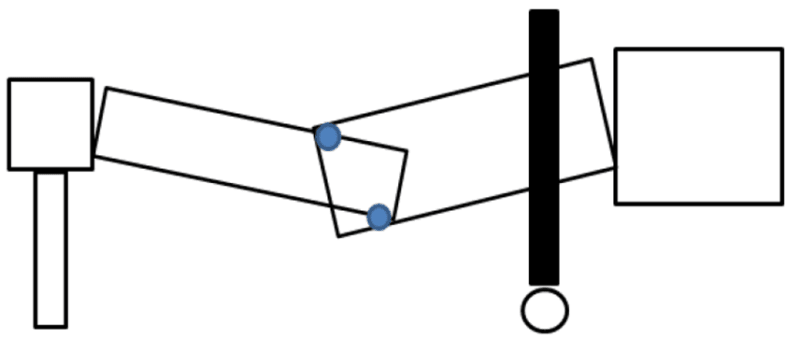
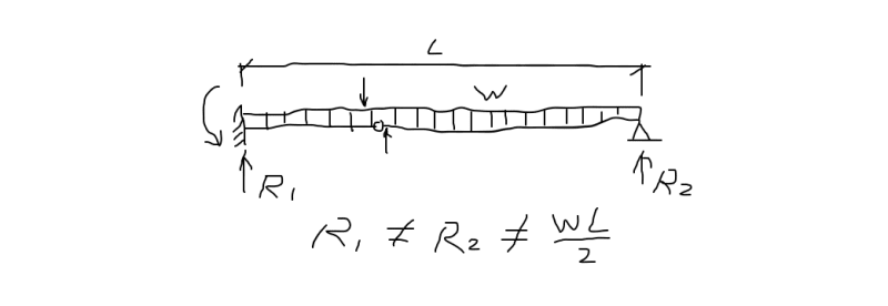
I wanted some clarification for how would the reaction loads at end supports and joint will be calculated in the case shown in the schematic diagram. The load of right structure would be supported by roller A however that load would also be transmitted to roller B. In this for value we can just assume that the uniform distributed load of the structure is 30 kg/m2 and distance horizontal distance between rollers is 1m. Thanks in advance.
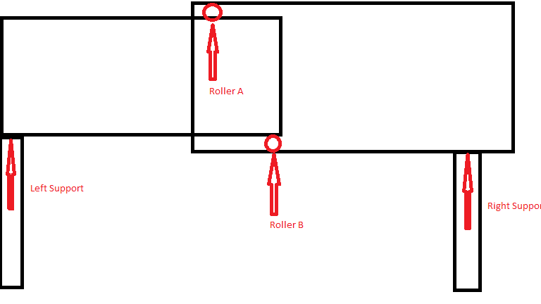
structure_yvzjdh.png
 
Replies continue below

Recommended for you

Sure, retired13, I can do that.

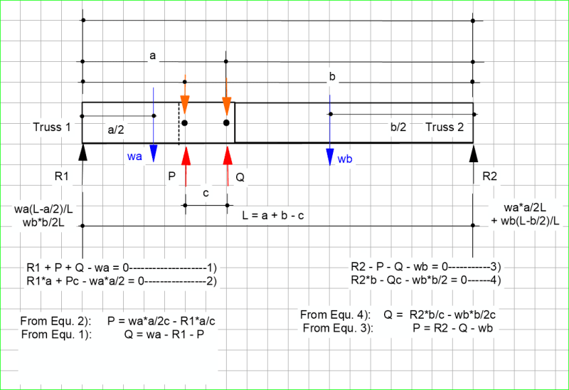
Edit: The following values were found for a = 4, b = 6, c = 2 and L = 8
R1 = 5.25 R2 = 4.75
P= -6.5 (the negative sign means the force is in the other direction from that assumed)
Q = 5.25


BA
 
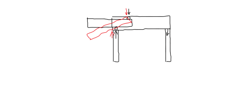
Thank you for your responses. I am still trying to get my head around that how do we take in to account the overlapping regions, the middle area where rollers are installed? Because technically weight would be multiple of a certain factor. I have drawn a schematic drawing based on the airport bridge, in a very exaggerated scenario I believe the rollers should be pushing down eachother and there is where there should be maximum deflection as well.
Picture1_nzegvu.png
 
I had an error in Equation 4) in my previous post...The sketch below has been corrected.

Overlapping_Trusses01_wdxxpv.png


BA
 
adjel said:
Thank you for your responses. I am still trying to get my head around that how do we take in to account the overlapping regions, the middle area where rollers are installed? Because technically weight would be multiple of a certain factor. I have drawn a schematic drawing based on the airport bridge, in a very exaggerated scenario I believe the rollers should be pushing down each other and there is where there should be maximum deflection as well.

I don't know what you mean by the sentence I have marked in red.

Your exaggerated scenario is more or less correct. The rollers cannot both be pushing down each other, but if the rollers are installed in the central area, you are correct in stating that maximum deflection should occur there.


BA
 
adjel,

I mentioned in an earlier post that the structure would be safer if, instead of having rollers A and B, you had hinges A and B and a roller at the right support. The way you show it is not wrong from a theoretical viewpoint, but you must make certain that the right support does not roll, even a little bit or your deflection will be much larger. If it rolls a lot, deflection will be all the way to the pavement.

You may find it easier to get your head around it if you consider each truss separately. What does Truss 1 need to stabilize it? What does Truss 2 need to stabilize it?

The answer is that, in both cases they need an applied moment to prevent them both falling to the pavement. This requires that forces P and Q on my sketch must be of opposite sign. Truss 1 needs a counter clockwise moment applied to its unsupported end. Truss 2 needs a clockwise moment applied to its unsupported end. This is good because one satisfies the other.

BA
 
BA,

Your results matches my finding in that the R1 and R2 are differ in magnitude, with heavier reaction at the support close to the pins. I must have made mistake in my equations, the reactions I got were R1=7.25W, R2=2.75W, and internal forces P=18.75W, Q=-22W,, obvious mistakes. When taking moment about support 1 and two respectively, there were two near identical small residual moments remained. Obviously I need to check my equations.
 
OP,

Operation of the airport boarding gallery system is similar to the opening and closing the desk drawer in our daily live experience. Without guide rails and rollers, the drawer will rotate, but will not fall out the desk through jamming, and/or our hand. With guide rails and rollers, the drawing maintains balance through out the movements through the force couple in the rollers.

p_ix3qcz.png
 
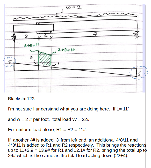
For the uniform load alone with L = 8', R1 = R2 = 4w

The overlap load is 2w and is centered 3' from the left end. This adds 2w*3/8 to R2 and 2w*5/8 to R1, giving a total of 4.75w and 5.25w for R2 and R1 respectively.

BA
 
EDIT: I was going to delete this post as it has no relevance to the topic, but as others have commented on it, I felt it was better to edit it instead. The problem here was a simple misreading of the handwriting; I mistook a '1' for a '2' (in two places). Sorry to add confusion to an already confusing post.

OverlappingTrusses_2_qm0skt.png


BA
 
BA,

The 2 was a "1", doctor's writing:)
 
Below is a familiar system that we all know the solutions. Though it is different from the OP's case, but there are parallels that bothers me - can we consider a linked beam as an integral beam when distribute the weight?!

p_hyzn2w.png
 
if the problem is a propped cantilever then we solve as statically indeterminate.

if the beam is SS then the solution is straight forward … A and B react the shear and moment imposed by the statically determinate external reactions and loads.

another day in paradise, or is paradise one day closer ?
 
Isn’t this just a telescoping simply supported beam? The roller couple has to resist the mid span moment.
 
Tomfh said:
Isn’t this just a telescoping simply supported beam? The roller couple has to resist the mid span moment.

Pretty much, but the overlap is not at mid span, so one roller force is slightly larger than the other. If the cantilever were taken into account, it too would have an effect. It's a problem in statics.

BA
 
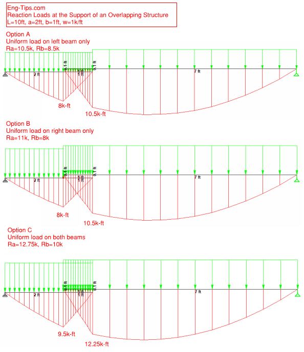
I have played a little bit with STAAD.Pro using Blackstar's dimensions. Beams are connected with dummy vertical members 0.1ft long. Below are 3 load cases:

Capture_xrqq4o.jpg
 
iv63,

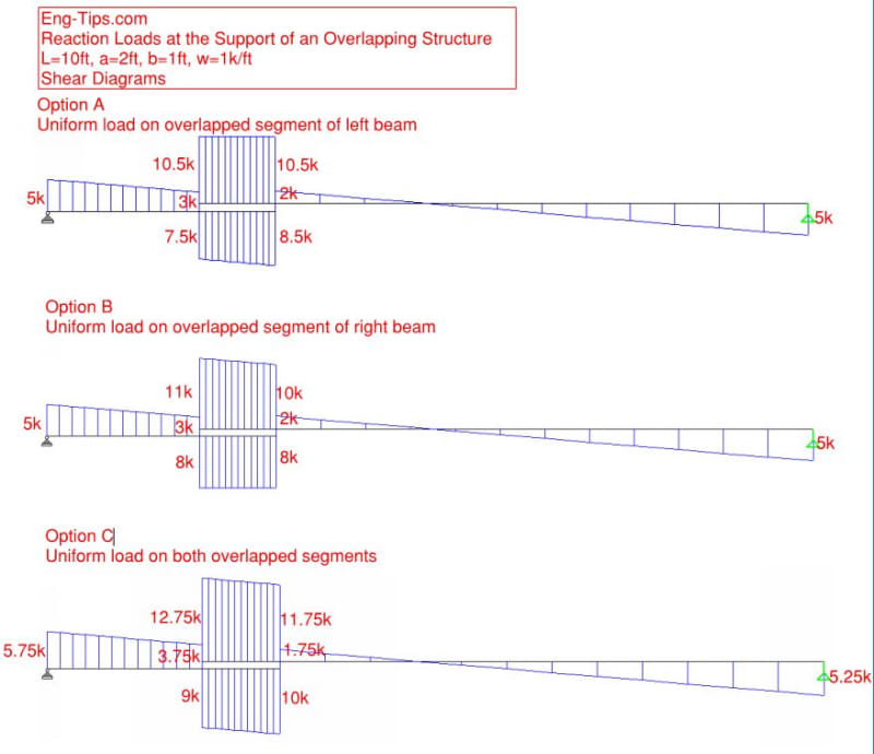
You stated the first and second cases consist of partial load, but the graphs show uniform load through out the span. The beam in Baackstar's example actually consisted of two segments - 8' on the right, 3' on the left, with 1' overlap. For w = 1 klf, the total applied load is ΣF = 1*(8+3) = 11 kips. Can you clarify and make one more run? Thanks.

Also, please show shear diaphragm too, which was the focus point in solving this system.
 
retired13,
Sorry for the confusion - I should have stated "Option A: Uniform load on overlapped segment of left beam" ...
Here are Shear Diagrams for all 3 cases:

Capture_bsw8nr.jpg
 
iv63,

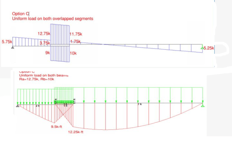
Thanks for sharing the results. I wonder the diagrams (shear, bending/reaction) below are corresponding to the same loading scheme?

d_ntgp6m.png
 
Excellent question. I'm fascinated by how many different approaches there are to the same problem. Not saying any are correct or incorrect, just different. It's enough to drive lawyers nuts. Here's mine, which I'll admit may have a math mistake, no time to check thoroughly. I'm somewhat interested how the solution looks when the rollers are near the ends.

[URL unfurl="true"]https://res.cloudinary.com/engineering-com/image/upload/v1587395298/tips/overlap_solution_z5ojza.pdf[/url]
 
Status
Not open for further replies.

Part and Inventory Search

Sponsor