Continue to Site

Eng-Tips is the largest engineering community on the Internet

Intelligent Work Forums for Engineering Professionals

  • Congratulations KootK on being selected by the Eng-Tips community for having the most helpful posts in the forums last week. Way to Go!

Roll center migration 1

Status
Not open for further replies.

Bluefoxy

Automotive
Apr 9, 2020
38
Hello,

I was wondering how roll center migration affects suspension performance during roll movement.

I have carried static suspension calculation, and I did not see any releveance of non migration roll center suspension, but my calculation are static not dynamic.

Do someone had experience on no roll center migration suspension and how it performs?

Regards

 
Replies continue below

Recommended for you

foxy said:
Mac Pherson works pretty well.

As only an amateur at this stuff, I suspect that a MacStrut works as well as it does . . . more in spite of itself than because of any kinematic virtue.

The fact that you have to introduce a virtual UCA to establish MacStrut kinematics in the first place (an artifact with a fixed angular relation to the knuckle, no less) ought to be a clue.


Norm
 
Norm,

I did not open this thread about Mc Pherson kynematics.

'The fact that you have to introduce a virtual UCA to establish MacStrut kinematics in the first place (an artifact with a fixed angular relation to the knuckle, no less) ought to be a clue.', English is not my native tongue, I did not understand the sense of what you mean, if you could put a drawing to explain, I will be thank full.
 
I realize that the MacStrut wasn't the original focus of this topic, but it's perhaps better to consider it anyway simply because a consistent approach to the usefulness of kinematic roll centers is either going to work equally well for the strut or weaknesses/limitations in the approach (small angle approximations more likely to become invalidated) might be more apparent because geometric roll center migrations are more severe with the strut suspension.

Pictures . . . the first is from Fred Puhn's "How To Make Your Car Handle (enthusiast-level book, 1976-ish)

The second is from a spreadsheet construction of my own.


Norm
 
Norm,

Thank you for the picture, I now understand what you met.

I will be happy to know your approach.
 
As y’all know, I don’t like the term “Roll Center”. I suggest:

The location at which the lateral force may be applied to create a roll moment about the center of gravity of the chassis equal to the chassis roll moment induced by the individual laterally loaded tires as transmitted through the suspension links to the center of gravity of the chassis.
It is a measure of chassis roll flexibility under lateral force, and it must be resisted by equal and opposite spring/ARB roll resistance.
 
yeah, I was looking at a website that somebody recommended for front view kinematics, and he'd put up a bug fix saying he couldn't figure out why it didn't roll around the roll centre. It gets even better when somebody connects the front and rear roll centres and calls it the roll axis.

Mind you to be fair Carroll Smith did include that in one of his books originally.

Cheers

Greg Locock


New here? Try reading these, they might help FAQ731-376
 
Buggar,

The location at which the lateral force may be applied to create a roll moment about the center of gravity of the chassis equal to the chassis roll moment induced by the individual laterally loaded tires as transmitted through the suspension links to the center of gravity of the chassis.

It is more or less the definition of Mitchell FAP (file attached).

I do not share this definition.
 
 https://files.engineering.com/getfile.aspx?folder=57b695a8-0a45-4a89-bfe7-2af98bf192c8&file=Vehicle_Dynamics2007_(1)_Mitchell.pdf
The useful definition of FBRCH is dFz/dFy*semitrack when a lateral force is applied at the contact patch. This is directly related to the idealised swing arm geometry and FVIC.

Cheers

Greg Locock


New here? Try reading these, they might help FAQ731-376
 
Greg,

You think FBRCH is an useful definition?
 
And you still see any any interest of my suspension with nearly constant distance from RC-COG?
 
Not especially, since I couldn't pick IRS vs Watts subjectively or objectively on smooth roads. It may be helpful, but it may be a small optimisation in the much bigger picture.

Cheers

Greg Locock


New here? Try reading these, they might help FAQ731-376
 
Greg,

You are agree with Mitchell, when he wrote: 'Stability results when the FAP-CG moment arm remains constant as the vehicle rolls. The chassis “takes a set” rather than constantly seeking a new equilibrium. This can be expressed by minimizing the lateral movement of the KRC as the vehicle rolls. But this is an artifact: there are more direct ways to calculate this; namely with the change in FAP height resulting from ride. It should be one-to-one. (An easier way to visualize this is from the viewpoint of the chassis rather than the world. The FAP point should be constant as the wheels and tires move up and down.)
 
Bear in mind that the FAP is most relevant for the side that is more heavily loaded (the outside wheel) because of the way the FBRCH is calculated. And for that ... I bring back your favorite topic ... the MacPherson strut.

The instant center will be somewhere along the line that is perpendicular to the upper strut mount. In most normal applications (certainly both of the vehicles in my driveway), that strut is only a few degrees away from vertical. So the instant-center will be somewhere along a few-degrees-off-horizontal line through the upper strut mount. With practical and sensible geometry (lower arm somewhere near horizontal at nominal ride height and not unreasonably short), that is going to lead to a FAP that is near ground level. The instant center of the unladen side (the inside of the corner) will be doing all sorts of screwy stuff, but it hardly matters because there's hardly any load on that side. So, the FAP-CG moment arm is going to be somewhere near the height of the CG give or take a little bit.

Out back, if I look at the two vehicles in my driveway right now, in one case it has a twist-beam axle, which will have a roll center (whether force-based or kinematic) not much above ground level, and in another case it has a suspension design that you will surely love ... a dead-beam axle on leaf springs! The roll center (whether force-based or kinematic) is at leaf-spring height. So in both cases, that CG to FAP moment arm doesn't change much.

Whatever ails the handling of both vehicles (and they've both got ailments), isn't because the roll center moves around with suspension movement ...
 
Brian,


As I far I understand, with few degree away from the vertical, It make an IC wich move on a line which nearly horizontal, which leads to a line Center of tire-IC, which is also quiet horizontal.
As the suspension compress (outside wheel) ,tire-IC went even more horizontal. So FAP of outside wheel does not alter a lot, and stay more or less near the ground.
As you do not care of the inside wheel, FAP of outside wheel become FBRC. And FBRC-CG remains constant.

If I well understand, according to you, a suspension which has an FBRC-CG constant is a suspension that is working well?
 
foxy said:
You are agree with Mitchell, when he wrote: 'Stability results when the FAP-CG moment arm remains constant as the vehicle rolls. The chassis “takes a set” rather than constantly seeking a new equilibrium. This can be expressed by minimizing the lateral movement of the KRC as the vehicle rolls. But this is an artifact: there are more direct ways to calculate this; namely with the change in FAP height resulting from ride. It should be one-to-one. (An easier way to visualize this is from the viewpoint of the chassis rather than the world. The FAP point should be constant as the wheels and tires move up and down.)
This "taking a set" . . . do you think that is strictly a displacement effect (geometric steady-state)? Or could it be an approximation of force equilibrium using a time history approach to forces associated with roll centers and the various elastic suspension components? Seems it might matter, since "taking a set" is something that the driver perceives.


Norm
 
Bluefoxy said:
If I well understand, according to you, a suspension which has an FBRC-CG constant is a suspension that is working well?

But there are a thousand other factors that are a higher priority.

Examples of suspension designs that have FBRC-CG dimension more-or-less constant in roll include: Rigid beam axle and leaf springs (both FBRC and kinematic RC at leaf spring height), pure trailing arms (both FBRC and kinematic RC at ground), swing axles (both FBRC and kinematic RC at swing axle pivot point height - which is fixed to the chassis i.e. the CG!), Ford Twin-I-Beam (instant centers at chassis-end I-Beam pivot points), double trailing arms traditional VW Beetle front suspension (FBRC and kinematic RC at ground).

Only car I know of with swing-axle-geometry front suspension:
Hark the Herald axles swing!
So here you have a collection of bad suspension designs that have FBRC-CG at least more-or-less constant in roll, if not necessarily in two-wheel bump or rebound.

And yet, MacPherson which is no better or worse than these in terms of that specific measure, works OK.

And if you wish to limit the discussion to upper-and-lower-wishbone designs ... A Formula 1 car has upper-and-lower-wishbone suspension layout. So does a 1955 Chevy. The F1 car is not particularly designed to keep the FBRC at constant height ... well, let me correct that. It does keep the FBRC at constant height (near ground level with almost-nil camber gain with suspension movement), by using brutally stiff springing and damping so that the suspension hardly moves, in which case, it doesn't matter!

Look at it this way. A FBRC that is slightly above ground level and doesn't move much in bump travel isn't something that you primarily design for, it is something that "falls out" when you impose all of the other things that you want the suspension to do in order to work the way you want it to work - and if it happens to move more than you'd like it to but your other constraints are satisfied, it doesn't matter.
 
Brian,

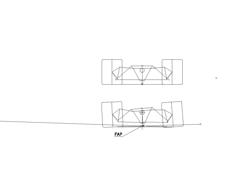
So I do not understand why you do not like the concept of twin arm suspension with constant distance RC-COG.
Because as far RC-COG remain constant, both FAP are very near (you even do not have to negligate the inside wheel), it result a FBRC -CG distance constant:
FAP_holj1r.jpg
 
Brian,

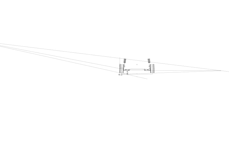
Regarding Mac Pherson,

I take the time to DRAW, because DRAW help me to understand what happen.
Regarding the position of FAP, it stay constant until the lower arm get the same angle as the perpendicular to the upper strut mount, if it come more angle it went totally opposit.
Drawing2_s49stn.jpg


Both suspension you mentioned with FBRC-CG constant ha a massive jacking effect.
 
It's not that I "don't like" that design.

It's that I'd rather focus my efforts on other things that achieve proper function, and let the roll center be wherever it ends up.
 
Status
Not open for further replies.

Part and Inventory Search

Sponsor