Continue to Site

Eng-Tips is the largest engineering community on the Internet

Intelligent Work Forums for Engineering Professionals

  • Congratulations KootK on being selected by the Eng-Tips community for having the most helpful posts in the forums last week. Way to Go!

Second case, profile callout

Status
Not open for further replies.

Andera

Mechanical
Jan 21, 2019
58
I got the following explanation seen below, but I would like to ask if you agree with the assessment? I see here are many GD&T experts that can help me with my follow up questions.
Unfortunately, the discussion I had, has been deleted on the original site, as the people there (original creators) I assume were not happy with the additional questions I’ve been asking them.


The second example is a refinement of Rule #1. As such, it would be inappropriate to have a basic dimension on the size.
If you are not familiar with the hierarchy of GD&T, Profile of a Surface, with a datum reference, can locate &/or orient a feature wrt the datums. Without a datum reference, if the feature is an enclosed boundary, then it will control size and orientation of the feature. If the size is already controlled, and a profile of a surface control is applied without a datum reference, it controls the form of the feature.
In the second example, what is being controlled is co-cylindricity of the 8 surfaces. The only geometric control that locates surfaces is .... profile of a surface.
If you're not familiar with the hierarchy, it's a good time to look at GD&T from that perspective.
I would like to see update the graphic to include a composite profile control as another option
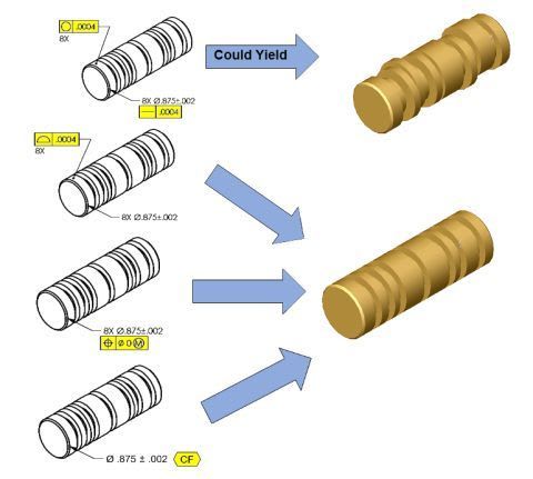


TE_-_Copy_txepnf.jpg
 
Replies continue below

Recommended for you

The quoted assessment is wrong.
For a closed shape with size or a pattern of such shapes such as a cylinder or a pattern of coaxial cylinders, the only case for profile not to control size is when the dynamic profile modifier is applied in accordance with ASME Y14.5-2018.
A profile tolerance needs a true profile, and in the second case, there isn't one.
 
In accordance with ASME Y14.5-2018 "When used as a refinement of a size tolerance created by toleranced dimensions, the profile tolerance shall be contained within the size limits." No mention of dynamic profile modifier.

Also, how use of profile in second case is different from use of profile on Fig. 11-16 ASME Y14.5-2018?

"For every expert there is an equal and opposite expert"
Arthur C. Clarke Profiles of the future

 
CheckerHater said:
Also, how use of profile in second case is different from use of profile on Fig. 11-16 ASME Y14.5-2018?

CheckerHater,
On example shown the feature is feature of size, so I think, the size is controlled by the profile, doesn't it?
On fig 11-16 the feature is not a feature of size so no issues controlling the size requirements/ or refine them.
 
Profile on the picture does NOT control size. It only controls FORM.

You have to understand that Fig. 11-16 is intentionally incomplete. Have you ever see drawings without any dimensions on them?

Important part of the picture is the idea of implied self-datum - it doesn't matter which aligned feature is measured in relation to which. Just like in case 3 position without datum works.

"For every expert there is an equal and opposite expert"
Arthur C. Clarke Profiles of the future

 
CheckerHater,

In dimensioning and tolerancing, there is a clear differentiation between surface controls and controls of abstract, resolved geometry such as axes and center planes. Where basic dimensions, explicit or implied, are required for definition of tolerance zones, they need to apply to the relevant type of geometry - surface, or resolved elements.

In figure 11-16, there is an implied basic dimension of zero between the two nominally coplanar surfaces. The profile tolerance zone is established based on a true profile that is defined by this basic dimension of zero. The basic dimension applies to surfaces. These surfaces are controlled by a profile of a surface requirement that uses the true profile as the basis for the tolerance zone.

In the OP example, there are nominally coaxial cylinders of non-basic size. An implied zero basic dimension between the axes defines the coaxiality. There are no basic dimensions, explicit or implicit, that define the surfaces. Since there are no basic dimensions that define the surfaces, there is no true profile, and a tolerance zone for profile of a surface can't be defined. Had there been a basic diameter, it would basically define the surfaces of the nominally coaxial cylinders. The true profile would be defined and profile of a surface could be applicable.

If the intent was to control only the form and the mutual orientation and location within the set of cylinders by a profile of a surface tolerance, a basic diameter would still be required, and a profile tolerance modified by the dynamic profile triangle would be appropriate for the purpose. But then, for the feature's definition to be complete, an upper single segment profile of a surface with a non-dynamic tolerance zone would be needed for controlling the size.

BTW - "Without a datum reference, if the feature is an enclosed boundary, then it will control size and orientation of the feature" (emphasis mine) is also a crude mistake.
 
"Since there are no basic dimensions that define the surfaces, there is no true profile, and a tolerance zone for profile of a surface can't be defined." - wrong. Profile can be used to refine toleranced dimension - it's in the Standard.

"Without a datum reference, if the feature is an enclosed boundary, then it will control size and orientation of the feature" (emphasis mine) is also a crude mistake" - I clearly said "FORM". Never claimed orientation.

In fact, big fan of this approach:
But we can argue indefinitely if we keep talking about two different things.


"For every expert there is an equal and opposite expert"
Arthur C. Clarke Profiles of the future

 
CheckerHater said:
Important part of the picture is the idea of implied self-datum - it doesn't matter which aligned feature is measured in relation to which. Just like in case 3 position without datum works.
Yes, I understand that.

I am not getting how for that feature of size the profile could control only the form error and not the size?
I am thinking that the actual surface should be between two coaxial circles .0004 apart, right? Then how the size is NOT controlled within .0004. That is my question.
 
Two coaxial CYLINDERS 0.0004 apart ... on which diameter?

"For every expert there is an equal and opposite expert"
Arthur C. Clarke Profiles of the future

 
CheckerHater said:
Two coaxial CYLINDERS 0.0004 apart ... on which diameter?

Are those two coaxial cylinders or circles free to float?
 
CheckerHater said:
- I clearly said "FORM". Never claimed orientation.

I didn't refer to something that you were saying. It was a BTW comment and the quote was from the assessment that was given elsewhere and brought to be discussed here in the OP. If I somehow made it look like these were your words, sorry about that.

CheckerHater said:
wrong. Profile can be used to refine toleranced dimension - it's in the Standard.
True, however it is never used for surfaces that have no applicable basic dimensions;
It is also in the standard that a profile tolerance controls a feature relative to a true profile.
A true profile is:
"the profile defined by basic radii, basic angular dimensions, basic coordinate dimensions, basic dimension of size, undimensioned drawings, formulas, or mathematical data, including design models"

As for examples of "refining" a toleranced dimension:
In figure 11-32 and in the "Orientation" case in your last attachment, there is a basic 0° (implied) orientation being controlled, relative to a datum.
I would say that the profile doesn't refine the toleranced dimension - it simply has nothing to do with it, as it controls a completely different property (orientation) than the toleranced (size) dimension. Moreover, the toleranced dimension and the profile are even applied to essentially two different features, even if the top surface is part of the top & bottom feature of size.
In the cone example - figure 11-19, the basic included angle of the cone defines the true profile, and no other dimensions are needed for the profile tolerance zone.
 
Without datum - change diameters and float while staying inside of size tolerance. That would be "Form"

With datum - change diameters while staying inside of size tolerance and maintaining axis - that would be "Orientation"


"For every expert there is an equal and opposite expert"
Arthur C. Clarke Profiles of the future

 
Also, there is no such thing as an "implied self datum".
In the position example, none of the aligned features is used as a datum feature for the control of the other 7 and there is no datum axis. The 8 features are best fitted into coaxial tolerance zones that exist independently of any datum, or evaluated for fitting into a common virtual condition boundary, that needs nothing but a calculable diameter to be fully defined.
 
Checkerhater, Burunduk and everyone,

Again, I am not understanding how do I know when a profile will control the size and form together or just the form (as stated by CheckerHater)?
 
In cases like this, I like to think about a questionable callout as if it had to be interpreted by a CMM.

So how could a CMM really know that the 8X profile goes together with the directly toleranced diameter? It simply couldn't. It would treat the profile as a size, form and possibly a "within-pattern-location" control applied to 8 basic .875 diameters obtained directly from the model and the +/-.002 diameter tolerance would simply be considered a redundancy.

The same issue would apply in the Orientation illustration from the last image attached by CH.

This is one of the reasons why solutions like these two should be avoided.
 
Andera said:
Again, I am not understanding how do I know when a profile will control the size and form together or just the form (as stated by CheckerHater)?

Consider a simple pin with two different tolerancing schemes.

Scheme 1: a basic dimension of ⌀20 mm is given as the pin's diameter, and a profile of a surface tolerance of 0.4 mm is specified, without any datum references. The tolerance zone is two coaxial cylindrical boundaries of ⌀19.6 and ⌀20.4.
In this case, profile controls size and form within the above-mentioned tolerance zone.

Scheme 2: a basic dimension of ⌀20 mm is given, and two single segments profile of a surface tolerance is specified. Both segments are without any datum references. The first segment is a 0.4 mm profile of a surface tolerance specification. The tolerance zone is the same as in 'scheme 1', and here too, size and form are controlled by the first segment (or, it may be considered that both size and form would be controlled had this been the only segment - but size is surely controlled by it). The second segment is a 0.05 mm profile of a surface tolerance with the dynamic tolerance zone modifier. The tolerance zone for the second segment is two coaxial cylindrical boundaries with 0.05 mm radial gap, which can adjust in diameter to accommodate any size of the actual as produced pin. The second segment, dynamic profile, controls (refines) only the form of the pin, essentially just like cylindricity would. So effectively the size is left for the first segment to handle, and the form is taken care of by the second, dynamic segment.
 
pmarc said:
So how could a CMM really know that the 8X profile goes together with the directly toleranced diameter? It simply couldn't. It would treat the profile as a size, form and possibly a "within-pattern-location" control applied to 8 basic .875 diameters obtained directly from the model and the +/-.002 diameter tolerance would simply be considered a redundancy.

And what would happen if the measurement is programmed without a CAD model? Would the profile requirement work at all without an input of basic diameter that normally results in a size (and form) control by the profile?
 
Y14.5 committee did not solve the issue for at least / or for the last 30-35 years. Should I say something more?
Dean Watts is very straight forward how he is interpreting these kind of ambiguous callouts.


Copy-paste
"The presence or absence of a basic dimension cannot affect what a profile tolerance controls. Only the static (fixed) nature of the profile tolerance zone and the capability of the referenced datum features affects what profile controls. If we allow the presence or absence of basic dimensions to affect what profile tolerances control, then we will have "achieved" the opposite of our objective, because we will have introduced ambiguity into the requirements for profile."


And one more from Evan J.
"Yes, you're right. We need basic dimensions for the true profile.
I hate to bring this up because I object to it, but there are examples in the standard in which profile is used along with a directly toleranced dimension. There's a figure where the line profile tolerance ends up acting like parallelism, I think. The usual location-controlling aspect of profile is magically overridden by the presence of the directly toleranced dimension. It's horrible."


Status
Not open for further replies.

Part and Inventory Search

Sponsor