Continue to Site

Eng-Tips is the largest engineering community on the Internet

Intelligent Work Forums for Engineering Professionals

  • Congratulations KootK on being selected by the Eng-Tips community for having the most helpful posts in the forums last week. Way to Go!

Simulation of a Single Datum Plane as Secondary Datum 2

Status
Not open for further replies.

donatim24

Mechanical
Jun 13, 2018
27
Hello,

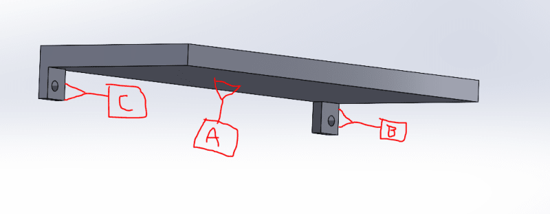
I have a part I'm detailing where a large, flat surface is my primary datum (A), and I would like to set two approximately (not quite, due to draft angle) perpendicular tabs as my secondary datum. The tabs have a significant gap between them. I would like to treat them using the method described in ASME Y14.5 Section 4.12.1/Figure 4-23 by calling the tabs datum B and datum C, and then calling datum B-C as my secondary datum. I would locate screw clearance holes (one hole on each tab) relative to A and B-C and name the holes datum D. However, all of the examples of applying Section 4.12.1 that I've seen in the standard and on GD&T websites only shows this technique being used for a primary datum. The one potential exception I've seen is the situation referenced in this post, but whether the simulated datum must be a primary datum was not the focus of the post:
Datum_Setup_aduqcm.png


Does ASME Y14.5-2009 allow for a simulated single datum to be applied as a secondary datum? I've attached a sketch to illustrate my question.

Thank you all!

Tim
 
Replies continue below

Recommended for you

Hi, donatim24:

You can use Combined Datum features as first, secondary or tertiary datum. However, the Combined Datum features that you selected are not good to control angular rotation DOF (Z direction). I assumed that your datum feature B and C are perpendicular. Please correct me if I am wrong.

Best regards,

Alex
 
Hi Alex,

Thanks for your response. In the example I attached (a dumbed down version of the actual model), the tabs marked datum B and datum C are perpendicular to the surface marked datum A.

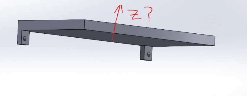
When you reference rotation about Z, are you saying that Z runs vertically through datum A (nominally "Up" in my screenshot)? Is the concern that the tabs are so small compared to the width of the part?

Axis_Question_xn5pni.png


Thanks,
Tim
 
For 2009, it appears it was "Multiple Datum Features" , 2018 is "Common Datum Feature" and farther back it was "Compound Datum Feature"

No need for consistency when training materials and training courses are the final product.

Anyway - if surfaces are used in combination to arrest motion then those surfaces can be selected and grouped, regardless of position in the datum reference portion of the feature control frame.
 
Hi, donatim24:

Yes. Z runs perpendicularly through datum A.

Is that true that datum feature B and C are perpendicular to EACH OTHER? If they are, then combined datum features (B-C) is not good to immobilize this rotational degree of freedom.

Best regards,

Alex
 
I apologize for the miscommunication. B and C are coplanar/parallel. I definitely agree that if they were perpendicular to each other, I couldn't use them as a single datum. Datum B and C are located on the wide faces of the tab with the clearance holes passing through them.

Thanks,
Tim
 
I see. Yes. You can use B-C datum features as secondary datum, or tertiary datum if you want to. But you will need an additional datum to locate other features on this part.

Best regards,

Alex
 
You can also use the CF symbol and treat them both as Datum B.
There's a bunch of cool ASME bells and whistles you can use.[bigsmile][bigglasses]
 
Thanks, Wuzhee. I wasn't 100% sure if I could use CF on a feature that's not a feature of size. It seems the standard (2009) is inconsistent in whether that's allowed.
 
I wasn't 100% sure if I could use CF on a feature that's not a feature of size. It seems the standard (2009) is inconsistent in whether that's allowed.
You can if there is some control locking the two surfaces to each other, such as flatness. Or even Rule #1 might suffice, as is apparently the case in Figure 10-32 of the 2018 standard.
 
The very minimum control you need is either a Datum Feature symbol, FCF or a size dimension. Then you can further combine them.
Take Fig. 5-11,12,13 from the 2018 edition. They are all sizes.

donatim24 said:
I wasn't 100% sure if I could use CF on a feature that's not a feature of size.
It is a FOS. Datum plane B is one size of that thickness, that must be treated as one. This raises the question as whether you want to treat the opposing plane as one surface also...

also ASME has two definitions, one is Continuous feature (like the datum plane) and Continuous FOS.
 
Status
Not open for further replies.

Part and Inventory Search

Sponsor