Eng-Tips is the largest engineering community on the Internet

Intelligent Work Forums for Engineering Professionals

  • Congratulations waross on being selected by the Eng-Tips community for having the most helpful posts in the forums last week. Way to Go!

Tourist submersible visiting the Titanic is missing Part 2 68

I wouldn't call blind arrogance admirable at all. Yes he put his money (and life) where his mouth was but his absolute disdain for other opinions or erring on the side of caution for such a dangerous environment is nothing to parade. He's just another rich person who, due to their money, thought they were the smartest person in every room and killed people because of that delusion.
 
RVAmeche yes, your analysis is true. And I believe others have posted similar.
 
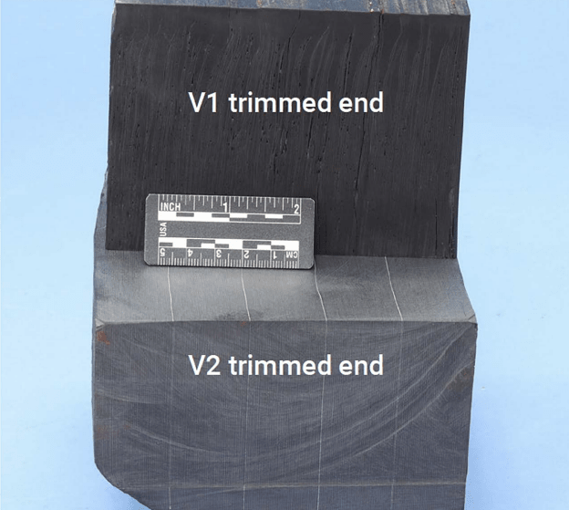
This may have already been known/discussed, but the NTSB showed that the two hulls were of completely different design: the v1 hull was monolithic (?) while the v2 hull was a series of shells bonded to each other with adhesive. Evidently these adhesive joints mostly failed during the implosion and the debris therefore consisted of the fragmented individual layers.

Interested to hear from those of you with CF experience regarding these findings.

2024-09-25_11_01_28-CG-107_NTSB_TITAN_MATERIAL_ANALYSIS.PDF_REDACTED.PDF_ustvxk.png
 
Karl Stanley summed up the problem with Stockton Rush's reliance on acoustic monitoring in one of the emails he sent to Rush in 2019 (after hearing sounds in the original hull that OceanGate eventually removed from service):
Karl Stanley said:
I also think you are relying too much on all the data, experts, testing etc that you cite. If the hull has a defect (which I believe strongly it does, as indicated by the sounds being concentrated in one area) the value you are placing on your "terabytes of data" goes out the window. If your next dive confirms that the sounds are concentrated in one area, is there any other conclusion than that one area has some sort of defect ?? Short of cutting the hull apart or testing it in a chamber to failure, how will you know what that defect is? If you don't know what the defect is, how can anyone predict how the hull will behave?
 
The 'V2' hull was wrapped and cured in stagess a direct response to the large amount of internal delamination/porosity seen in the first hulls constructed (both full scale and test) which were wrapped and cured in one go, using a wet layup. This decision is covered in other documents released as part of the hearing.

I would think that obtaining the same strength as a monolithic part would be possible, given sufficient/correct prep of the in-place cured surface... but I've only ever dipped my toe in the composite design pond, I wouldn't call myself an expert.

 
Oh my, it gets worse:

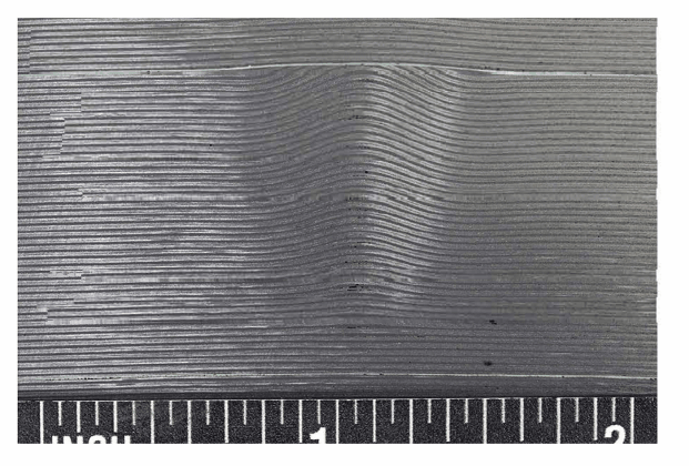
TitanHullWrinkle_kdhmg5.png


Not only are there nasty wrinkles that significantly reduce the compression strength, but some idiot decided it would be a good idea to machine them flat, thereby cutting the very fibers they are counting on to carry the load. UGH.

And then this gem:

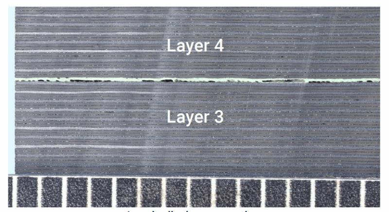
TitanHullVoids_uby6zl.png


A "nice" planar disbond along the adhesive line. Great.

The hull fragment photos later in the doc show the hull clearly disbonded along the adhesive layers. Probably too complicated to tell if that was the initial fracture or not.
 
The fabrication methods shown were machine-controlled layup systems over a metal mandrel by companies that seem to be specializing in fiber-reinforced fabrication. What causes the wrinkles and delaminations and air pockets? Is it heat effects due to the exotherm of the binding resin or heat used during curing? Is air trapped within the wetted fibers during winding? Is the 5-inch thickness difficult to cure evenly?
 
Brian Malone said:
Is the 5-inch thickness difficult to cure evenly?

Most definitely. That's why they changed to the multi-cure approach in the first place.

The fabricator of the hull was definitely experienced in CFRP mandrel-wound fabrication, but I'm not sure they (or potentially, anyone on planet earth) were experienced in mandrel wound composite structures of this thickness. A lot of these problems are directly due to the difficulty in winding a part with walls this thick and getting a very low void result.

I think this is compounded by the fact that the overwhelming majority of mandrel wound CFRP pressure vessels are subjected to internal pressure in service. You would never want there to be voids in the layup, but if the assembly is under tension, voids are going to have much less negative impact on performance.
 
This appears to me in order to limit air entrapment and voids the layup should have been done in a vacuum chamber. The resin obviously would be degassed and the fiber stock would be allowed to outgas before starting the wrapping. The continuious feed-stock would have to be degassed and passed into the fab chamber. And the layup process would have to be fully automated; which it appears this is already the case for FRP-type cylinders. There are large vacuum facilities available. Are any CFRP structures fabbed in a vacuum environment?
 
That's a great way to make an already expensive process more expensive by a factor of probably at least 3.

That also wouldn't solve the problem. Epoxy outgasses when it cures. Control of negative pressure on the parts is a critical aspect of making composite parts successfully. This isn't an issue on smaller components because the outgas products can migrate through the matrix as the part cures- but the thicker the parts are, the longer that takes, and it is possible to cook CFRP parts for too long and negatively impact net properties.

There is an upper limit to how thick you can make CFRP parts.
 
SWC, I see only 4 fibers of many cut by the machining. Do you think the cutting of the 4 fibers compromised the strength more than allowing the defect to continue through the rest of the layup?
 
The cut fibers,
- cause a local stress concentration in the laminate as load has to shift to adjacent layers,
- cause a stress concentration in the adhesive bondline, which is already compromised by porosity, voids and general poor quality

How much the cut fibers degrade the overall strength is near impossible to predict, without some test data to calibrate the prediction.

The fiber waviness thru the thickness results in reduced compression strength (like a pre bent column with a axial compression load). This is also hard to predict.

And they apparently designed the laminate to wildly optimistic ultimate strain levels (that essentially assume perfect laminates with no defects or variations).

Then they essentially fatigue loaded the hull to very high strain levels by repeated trips to depth. A hull that had lots of defects in it.
 
So OG was iterating the hull design and using the only hull for missions. And they had changed hull manufacturer from Spencer Composites to either ElectroImpact or Janicki. Has the manufacturer been determined? Without testing an actual hull to implosive failure with full instrumentation I do not see how they could have confidently had an acoustic and strain signature that could be used in a predictive manner. I think if the design team had video, acoustic and strain data of a full size hull implosion, the speed and totality of such an event would have been real and not theoretical. The apparent normalization of implosion risk might not have occurred and more caution would have been used for proceeding to manned missions to full depth.
 
Have any photos of the interface rings been presented? I have zoomed in on the wreckage photos and rhe limited view of the hull interface recess in the rear ring is pretty obscure. The front ring hasn't been shown, has it?
 
@TugboatEng in addition to SWC's comments above - that's not 4 fibers cut; that's millions of cut fibers.

Published docs show they were using roughly 133 layers per inch. Each layer is a wrap of whatever tow they used - that's an unknown, 18k or 24k tows that are 25mm or so wide would a typical choice for a fiber pressure vessel. That means 24,000 fibers per layer x 8 layers cut x depth of that discontinuity in the thirds axis. It's a lot of fibers.
 
The two reports on the NTSB website go into more detail than the summary on the USCG MBI website. The outer surface was very wavy and there were very many locations where the wrinkles had been ground to allow the next layer to start without wrinkles.

The NTSB report noted a loud bang at the end of dive 80 (after the sub had surfaced), which resulted in a noticeable change in the strain response of the hull (including a new nonlinearity that was shown at the start of the next dives). The NTSB report also noted that the adhesive surface between the end of the hull and the ring had a rubbed beginning near the base of layer 4 and continuing radially inward. This may indicate that about 3/5 of the adhesive had disbonded long before the failure.

Failure sequence guess:
1. Event at the end of dive 80 causes significant damage, either to the adhesive or hull itself.
2. Dives 81-83 show signs of this damage and might slightly increase it, but not enough for failure.
3. Sub is store outdoors for the winter and then handled roughly (towed on LARS behind the ship; at least 3 upset events while towing in addition to the banging of the waves) - this exacerbates the damage so the sub is no longer suitable for full depth.
4. Sudden implosion without warning on dive 84, due to adhesive disbonding between the hull and end rings and/or buckling of the hull (which had voids, delaminations, waviness, and cut fibers to begin with, and some of these weak points had likely grown due to the cyclic load and impacts suffered by the hull).
 
From jmec87's link:

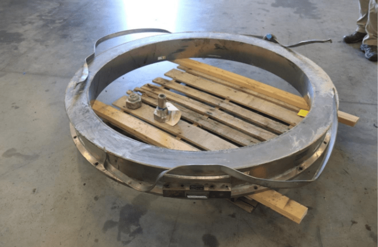
Screenshot_20240926-120231_p4eh31.png


The inner location flange failed in shear as the bond between the hull and some failed which is expected. But the outer flange failed in bending and bent outwards.

Having the two flanges is a terrible design as it traps air and doesn't let excess adhesive flow out.
 
Wouldn't the flanged design be a benefit if the relative compressive response of the hull cylinder ends and the interface rings can be matched. I believe the necessity for this behavior was discussed by 3DDave at 9//2024. The inner flange would limit the shear load on the adhesive. Mechanical interlock of the hull ends to the interface rings would be a necessity. Regardless of any 'bang' that may have been heard, the acoustic monitor location diagrams don't show any strain instrumentation at the interface surfaces or on the interface rings. The sensor are along axial lines of the hull and arcs of the end domes, and at the circumference of the inner edge of the viewport. Mechanical failure at the interface zones was not being monitored. The epoxy is wiped clean off the forward interface ring.
 

Part and Inventory Search

Sponsor

Back
Top