Continue to Site

Eng-Tips is the largest engineering community on the Internet

Intelligent Work Forums for Engineering Professionals

  • Congratulations SDETERS on being selected by the Eng-Tips community for having the most helpful posts in the forums last week. Way to Go!

Truss Reactions

JStructsteel

Structural
Aug 22, 2002
1,422
So got truss reactions as a lump sum, i.e. not broken into DL, LL, WL, etc.

Is it worth figuring out the components, or just design for the total reaction using ASD?

I asked for the component reactions, but got no reply.

Thanks
 
Replies continue below

Recommended for you

Yeah, I don't think the MiTek and other similar softwares are capable of breaking it out. And you're not working with an engineer - it's a designer who may be very knowledgeable (@RontheRedneck ) or may have no clue what load combinations are. The engineer is just rubber stamping the output after the fact. They probably couldn't tell you where a single truss they've "designed" is going to be installed.

Just apply it with ASD and roll with it. If you have complex framing with lots of transfers, then it might benefit you to work out loading for yourself so you can break it down.
 
I'd probably break it down into the components. This will also serve as a good double check of their loads/reactions.
 
No one has ever asked me for reactions to be broken out before. The program does not give us any control over what appears on the drawings.

It might be possible to get them by printing out calcs for each load case. I've never tried it. If I think of it tomorrow I'll give it a shot.
 
No one has ever asked me for reactions to be broken out before. The program does not give us any control over what appears on the drawings.

It might be possible to get them by printing out calcs for each load case. I've never tried it. If I think of it tomorrow I'll give it a shot.
In Canada where we use LSD we get them broken up by type all the time. If/when you guys ever switch to LRFD only, you'll likely see more of this.
 
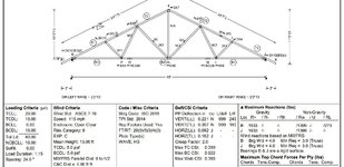
Just for the heck of it I ran a 40' truss today. This is what the program came up with for a shop drawing.


Example truss.jpg


There's an option to print calcs to a PDF file. You should find it attached if you care to take a look. But it's almost 40 pages of stuff based on all the load cases. And for the most part reactions are not spelled out.
.
 

Attachments

  • Example_calcs.pdf
    478.4 KB · Views: 6
Maybe I am oversimplifying the problem, or maybe I'm just dumb, but can't one just take the tributary load to one truss and use statics to get the reactions by load case?
 
Just for the heck of it I ran a 40' truss today. This is what the program came up with for a shop drawing.


View attachment 7684


There's an option to print calcs to a PDF file. You should find it attached if you care to take a look. But it's almost 40 pages of stuff based on all the load cases. And for the most part reactions are not spelled out.
.
Can't you just take the VERT(TL)-VERT(LL) to find VERT(DL) anyways with this? It basically is broken up into components.
 
And for the most part reactions are not spelled out.
Yeah - looks like you have a load case for "IBC" which I'm guessing is the worst case gravity combination for the overall truss, about 14 different wind cases, a dead load only case, and a wind and dead load case.

but can't one just take the tributary load to one truss and use statics to get the reactions by load case?
Yes and no. You can do that and get close enough to design a safe and reliable structure, but I've never managed to get it perfect - especially when dealing with more than 2 bearing points. It's just a bit irritating that they can run these trusses in such a powerful program, but there's no option to give the raw data needed to produce an efficient design for the rest of the building.
 
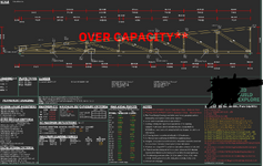
Yea, I mean look at this truss. The right end (14) is supported by a girder truss. I asked them to provide a bearing at 15 (interior wall) to take some load off the girder but it is barely taking any load (131 lbs). If their software took into account the actual deflection of this truss and the carrying girder truss (14), the reaction at 15 would be a lot more.
 

Attachments

  • Pages from Magnolia LH Elev B V4 Drawings.pdf
    572.2 KB · Views: 12
Last edited:
Yes and no. You can do that and get close enough to design a safe and reliable structure, but I've never managed to get it perfect - especially when dealing with more than 2 bearing points. It's just a bit irritating that they can run these trusses in such a powerful program, but there's no option to give the raw data needed to produce an efficient design for the rest of the building.
Wow! After 48 years, I'm finding out statics is no longer a valid analysis technique! I'm not sure what your definition of perfect is, but one should be able to get reactions of either a statically determinant or statically indeterminant beam by statics.
 
Throwing my hat in here, I always just ratio the given reaction. Is it a perfect solution? No, but it's close enough to satisfy me.

If a reaction is give as 1387lbs, and the design loading overtop is 15psf TC DL, 5psf BC DL, 20 RL, 35 SL, I'll just assume a worst-case load combo (DL + SL) and us the total roof loading ratioed down to break down the reaction into component loads.
 
I asked them to provide a bearing at 15 (interior wall) to take some load off the girder but it is barely taking any load (131 lbs).
Actually looks like that 131# is a tension reaction [upsidedown]
 

Part and Inventory Search

Sponsor