Continue to Site

Eng-Tips is the largest engineering community on the Internet

Intelligent Work Forums for Engineering Professionals

  • Congratulations KootK on being selected by the Eng-Tips community for having the most helpful posts in the forums last week. Way to Go!

Two Parallel Datum Features defining a Single Datum Plane?

Status
Not open for further replies.

Th.Ro.

Mechanical
Apr 2, 2019
23
ASME Y14.5-2009 has this for Two Coaxial Datum Features defining a Single Datum Axis:
Single_datum_Plane_from_2_reference_surface_sets_2_daqevd.png


Would it be OK to use this also with 2 sets of parallel planes like this:
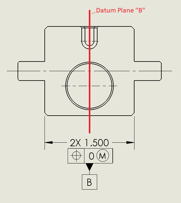
Single_datum_Plane_from_2_reference_surface_sets_1_ndggbu.png
 
Replies continue below

Recommended for you

Sure, I don't see why not.

I am assuming also that the centerplanes of interest are not only parallel but coplanar.
 
Yes, they should be coplanar as if they were made as one surface.
It is somewhat a continuous feature situation, only that I don't think you can actually apply the continuous feature symbol here as it isn't really a feature created in one "cut".
 
It is somewhat a continuous feature situation, only that I don't think you can actually apply the continuous feature symbol here as it isn't really a feature created in one "cut".

Not entirely sure what you mean. If you're referring to the manufacturing process that does not matter. Maybe a different drawing view/model view would help explain what you mean.
 
It is my understanding that there are issues using CF for planar features, but I don't think that would apply here as you have them qualified to each other.

"Know the rules well, so you can break them effectively."
-Dalai Lama XIV
 
ewh,

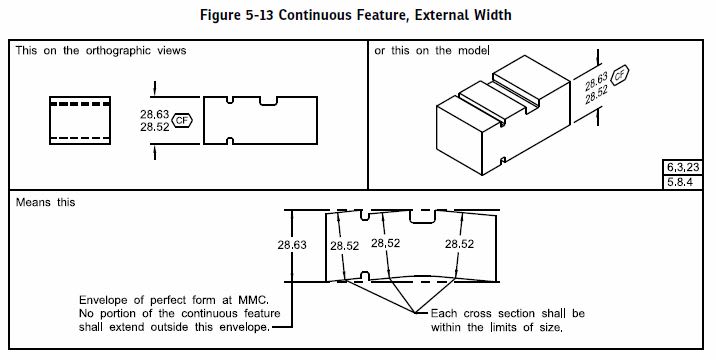
Do you mean planar or width-shaped? Planar yes I agree - especially since CF specifically requires it be applied to a FOS*. If you mean width-shaped - both Y14.5-2009 fig 2-10 and Y14.5-2018 fig 5-13 show CF utilized with a width-shaped feature.

5-13_o4yg4k.jpg


*Edit - I spoke too soon. As long as the planar features are related to each other somehow (ie: a profile tolerance) one should be able to apply a continuous feature. 2018 makes this clear. This isn't the OP's case though, looks like they have 2X width-shaped FOS.
 
As I understand it, a continuous feature is a feature interrupted by a gap or cut (as shown in figure 5-13 above), but not by a protrusion. At least that is what all the examples in ASME 14.5Y suggest.
 
Th.Ro.

Ah yes, that seems to be the current interpretation. For some reason I missed that on your drawing.

There is an attempt to better define this in Y14.5-2018 as the definition for continuous feature in 2018 includes the term "interruption" which is further defined in Y14.5-2018 section 3.39 as "a gap or gaps in a feature that divide it into two or more features (e.g., a slot or a groove)." Though I think this definition still leaves something to be desired, the consensus is I believe as you say - that features separated by protrusions of the material as in your drawing cannot be used with <CF>.
 
Th.Ro.,

I agree that your example in the original post is acceptable.

Note that it doesn't matter whether the feature midplanes are nominally coplanar, or even nominally parallel, as long as the basic relationship between them is defined. That relationship is defined entirely with implied zero basic dimensions in ASME Y14.5-2009 Fig. 4-24 and in your example, but Fig. 4-26 is an example of the same concept where explicit basic dimensions would be required.


As I understand it, a continuous feature is a feature interrupted by a gap or cut (as shown in figure 5-13 above), but not by a protrusion. At least that is what all the examples in ASME 14.5Y suggest.

That may be what the examples in ASME Y14.5-2009 happen to show, but I wouldn't say they suggest it's a requirement. The actual text of para. 2.7.5 certainly doesn't suggest any such thing. I see no problem with using <CF> instead of 2X and the position tolerance in your example.


pylfrm
 
pylfrm,

I would agree that the text itself of Y14.5-2009 does not prohibit the practice of using <CF> across "protrusions" as well as "gaps" besides not including examples of both in the figures. However it seems like the 2018 standard attempts to clarify the term "interruptions" utilized in the definition of continuous feature in section 3.39 to prohibit protrusions. Now if one were to say this is a sub-par attempt at doing so, I would tend to agree and would like to have seen a bit more rigor injected into this statement (replace the term "gaps" with literally almost anything more descriptive/specific - perhaps discontinuities which do not cross the boundary established by the continuous feature - I'm just spitballing here though). *Edit - I want to remove what might be misconstrued as heresay. I only meant to communicate that from conversations the consensus I have experienced was that the "gaps" mentioned in 2018 would preclude "protusions" of the type shown in the OP, however this may not be shared everywhere and I am very open to alternate interpretations - indeed I am not fully convinced myself that this would have to be the case besides if the text of the standard expressly forbode it (which it maybe attempts to, but poorly as I said).

Th.Ro.

Whatever you decide to do - just a matter of note of which you may be aware that the control with or without <CF> is not 100% equivalent. <CF> essentially preserves rule 1 and the associated control of form/size deviation across the interruption(s).
 
chez311,

I still haven't seen the actual 2018 standard, but I don't see anything in the draft suggesting that the gap(s) between portions of a continuous feature must be free of material.

I also don't see any benefit in adding that restriction.


pylfrm
 
ASME Y14.5-2018 said:
3.39 INTERRUPTION
interruption: a gap or gaps in a feature that divide it intotwo or more features (e.g., a slot or a groove).

ASME Y14.5-2018 said:
6.3.23 “Continuous Feature” Symbol
The symbolic means for identifying two or more interrupted features or interrupted regular features of size as a single feature or feature of size is shown in Figure 6-12. The “CF” symbol shall be applied to a size dimension of an interrupted regular feature of size, adjacent to a geometric tolerance for an interrupted surface, or adjacent to a datum feature symbol applied to interrupted features. When using the “CF” symbol, the extension lines between the features may be shown or omitted; however, extension lines by themselves do not indicate a CF. See Figures 5-11 through 5-13 and 10-32, and para. 5.8.4. The number of surfaces (n) that are included in the CF, such as “n SURFACES,” may be added beside the “CF” symbol.

These are the relevant parts of the new standard which tie together the definition of interruption with <CF>. I think interpretation of the definition to disallow protrusions relies on the connotation of the word "gap" to mean void, the inclusion of "e.g., a slot or groove", and examples which only include these types of "gaps".

From discussions I've had in the past, it seemed that there was some that were under the impression that <CF> should create an continuous boundary which is either expanded/contracted around/within a FOS (UAME) though this breaks down slightly with a nonsize/planar feature - i guess the analog would be progressing towards a planar (or other nonsize) feature. Any interruptions that would hinder this behavior or contact the boundary before it contacts the surface of interest (ie: a protrusion) would preclude the use of <CF> in those cases.

For what its worth I was not quite sold on this point. I understood what the reasoning was, but did not understand why it had to be this way - especially since the wording of the standard is not (in my mind) explicit, but interpretation in this manner relies on implications/connotation.

Basically long story short, I agree with you but I think that might be a minority opinion.
 
pylfrm,

Just to expand on this, the main thrust of the opposition to using <CF> in cases of protrusions comes from what I mentioned as a "continuous boundary" - ie: that the UAME (or similar perfect boundary) of a continuous feature should be uninterrupted. Additionally I think there are practical concerns ie: that a <CF> should be created in a single "cut" as OP mentioned, and that it makes gauging difficult. To the first I would say that a tolerance/control should be production method agnostic - and also that there are production methods that do not create a feature in a single "cut" but might want to be controlled as such (3D and 5axis milling, 3D printing, among others). To the second I would say that it may be difficult but not insurmountable, and virtual simulation would make quick work of such a feature.

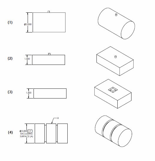
As a thought experiment I created the below example to challenge the idea requiring a UAME to be a continuous, uninterrupted boundary. My inquiries were:

- Do (1) and (2) have a UAME?
- What about (3) ? If that "island" is on the same plane (or even below) as the top surface but the tolerance on it (however its applied) could allow variation that would interrupt closing of a UAME upon the top surface if the UAME must be continuous.
- (4) is a variation on (3) with a similar concept, but with <CF> applied and the features fully separated by grooves.

To be clear as I said I don't really have a fundamental opposition in using <CF> in OP's case, and it seems to me that all 4 of my examples should have a valid UAME which can be violated by the features which it does not control (protrusions). The area that might throw this into question is Y14.5-2009 section 1.3.25 description of "envelope, actual mating: this envelope is outside the material" and Y14.5-2018 section 3.29 describing an AME as an envelope that "is on or outside the material" - what do you think? Even if this definition ruled out (1) and (2), my (3) and (4) would still be problematic.

CF_and_UAME_jme6sh.jpg
 
If the thinking is that <CF> shouldn't be used with protrusions simply because it doesn't create a touchable boundary, then the same logic should dictate that LMB never be used on a datum reference. You can't make a physical simulator for LMB, yet we all seem to have no problem with that concept (in theory, though not often practical).
Just my 2 cents...

John-Paul Belanger
Certified Sr. GD&T Professional
Geometric Learning Systems
 
JP,

Thats actually a good point and taking it from a perspective I wasn't even thinking about. It can also be used to extrapolate the point about interruptions and the AME - a primary datum feature referenced at LMB would presumably require an AMME or Actual Minimum Material Envelope defined, and the same way a AME external to the material would have to "avoid" or "ignore" protrusions a AMME would have to do the same to gaps/grooves/slots - for example the secondary datum feature B in Y14.5-2018 fig 7-23.

All the more reason to believe that an AME and by extension <CF> can be utilized in cases of these protrusions - even if such protrusions separate it into two separate features as in the OP's case.
 
To be clear as I said I don't really have a fundamental opposition in using <CF> in OP's case, and it seems to me that all 4 of my examples should have a valid UAME which can be violated by the features which it does not control (protrusions). The area that might throw this into question is Y14.5-2009 section 1.3.25 description of "envelope, actual mating: this envelope is outside the material" and Y14.5-2018 section 3.29 describing an AME as an envelope that "is on or outside the material" - what do you think? Even if this definition ruled out (1) and (2), my (3) and (4) would still be problematic.

The envelope only needs to be outside the material of the feature to which it applies.

I think it usually makes most sense to consider these boundaries or envelopes as having infinite extent. That would be a cylinder of infinite length for your examples (1) and (4), or a pair of infinite parallel planes for (2) and (3). Looking at it this way, it doesn't matter whether a protrusion is in the middle of the feature, adjacent to it, or somewhere far away.


pylfrm
 
Status
Not open for further replies.

Part and Inventory Search

Sponsor