Continue to Site

Eng-Tips is the largest engineering community on the Internet

Intelligent Work Forums for Engineering Professionals

  • Congratulations KootK on being selected by the Eng-Tips community for having the most helpful posts in the forums last week. Way to Go!

Two-slider crank mechanism 9

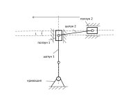
To create faster and more economical internal combustion engines, I propose to use my invention - Riyanov double-slider crank mechanism (Two-slider crank mechanism). I received 4 patents in Russia (№ 2634851), China (№ 3349271), Japan (№ 6373516) and the UK (№ 3530879) for my invention, which can be used to create more environmentally friendly and faster engines, generators or in other projects.

SUBSTANCE: crank double-slider mechanism includes a crank, two connecting rods and two sliders. The second connecting rod is connected to the first slider at one end, and to the second slider at the other end. The second connecting rod length is equal to the sum of the double crank length and the distance between the connection point of the second connecting rod with the first slider in the initial phase of its movement measured in the direction of the first slider travel and the longitudinal axis of the second slider.
EFFECT: ensured full turn of the crank in one stroke of the extreme slider in the chain in one direction.

The unconditional effect of the two-slider crank mechanism is overcoming the limitation in the number of revolutions per minute in the internal combustion engine for the same working stroke of the slider, which can be used in internal combustion engines requiring high speed (for example, drones (land, air, water), subcompact cars, motorcycles), as well as in electric generators based on internal combustion engines, wave electric generators.

The key predicted effects are a gain in speed, a reduction in fuel consumption, the use of fuel with a lower octane number as a result of an increase in the working stroke of the slider, simplicity of design (gears are not used to double the speed).

I propose to use internal combustion engines based on the proposed mechanism primarily in unmanned aerial vehicles.

The subject of discussion is the possibility of practical application of the proposed mechanism in internal combustion engines.

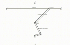
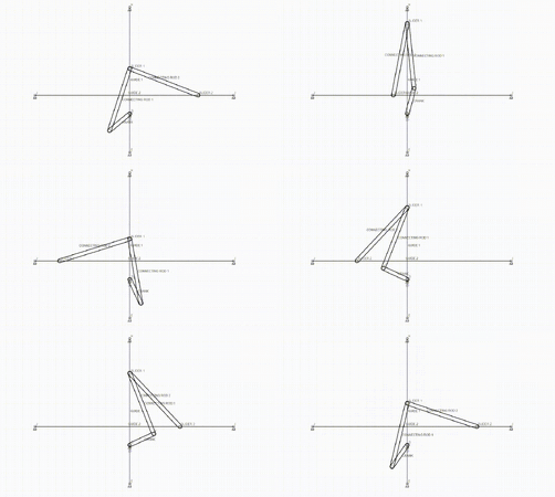
In existing internal combustion engines, the crankshaft makes half a revolution per stroke of the slider in one direction. In the proposed mechanism, it makes a full revolution per stroke of the outermost slider in the chain in one direction.Two-slider crank mechanism.jpgTwo-slider crank mechanism - animation.gif
 
Last edited:
There are a couple of areas where a new invention is useful or valuable.

1) It does something that has not been done before
2) It improves something that is already being done.

This is supposed to be a connection between a piston and a crank. That has been done before.
The novelty of the particular way may not have been done before, but it is not an improvement.

Were previous researchers interested in running low rate pistons to turn high rate cranks and found that useful, they would have used gears. This is how some generators work, but they have more than a 2:1 improvement. The vast majority of cases is to turn high rates at low torque into low rates at high torque, the opposite of this.

Find someone to build a prototype, even a mainly 2D mechanism, and prove that it is an improvement. I think you will find the additional friction will prevent it from moving properly, but I also think that by the time you make a sloppy enough mechanism to not lock in position it will not be suitable for use as a motor.

As always, it is up to the inventor to overcome the objections of the doubting audience, a task normally done by building a device that works.
 
One full revolution of the crank shaft per stroke of the slider, I got that part, but again WHY do I care about this slider?


Engines that can rev very high have very LOW reciprocating mass. So again, why is ADDING mass with this slider going to help me spin the engine faster? Not just "because it will", give me some physics behind it. Gearing is irrelevant.


Suck - squeeze - bang - blow --> these are the 4 fundamental steps to the 4 stroke combustion engine. Your slider doesn't change any of that. For simplicity sake, you have 180deg of crank rotation for intake as the piston goes down, 180deg as it goes back up for compression, 180deg as it goes down during combustion, and 180deg as it goes up during exhausting. Your combustion period can only be for half a rotation, and that can only be every-other rotation. Adding and extra arm moving around up top doesn't change any of your valve timing. Aside from the fact that this will all be much more complicated as you now have to make room for these parts to accommodate your slider arm.

Also, there is a LOT of math that goes into balancing the pistons and the crank to each other to reduce/eliminate vibrations and moments. Your slider mass up top there is going to violently shake the engine back and forth.
Watch the animation of the mechanism. In one stroke in one direction of the outermost slider in the chain (it is also the piston in the internal combustion engine), the crank makes a full revolution. Vibrations can be compensated by the opposite arrangement of the two mechanisms.
 
In one stroke in one direction of the outermost slider in the chain (it is also the piston in the internal combustion engine), the crank makes a full revolution.

My understanding is the point of making this is that you can achieve higher crank RPMs as you are getting an additional crank rotation per piston stroke cycle. Presumably, you are trying to do this because engines fail when pushed to high RPMs. Lets say you can get a piston moving up and down 6000 times a minute before failure, matching a 6000 RPM crank speed. Now, we take a similarly sized piston and put it in your motor, and try to push that piston once again to 6000 cycles per minute, because we are assuming that to be our limiting factor. Your crank is spinning at 12000 RPM, which I know you say you want to achieve those higher RPMs, but your connecting rods and rod pins have to be able to support that connection. Not only is that an issue itself, but the connecting rod from your combustion piston and your middle slider, due to the necessary geometry, that will be a very long connecting rod making it susceptible to bending and other similar failures.

This will have enough mass and awkward geometries that it will be running at the same low RPMs as a diesel.

Vibrations can be compensated by the opposite arrangement of the two mechanisms.

In principle you are correct, just fyi that is much harder to do than I think you anticipate.
 
My understanding is the point of making this is that you can achieve higher crank RPMs as you are getting an additional crank rotation per piston stroke cycle. Presumably, you are trying to do this because engines fail when pushed to high RPMs. Lets say you can get a piston moving up and down 6000 times a minute before failure, matching a 6000 RPM crank speed. Now, we take a similarly sized piston and put it in your motor, and try to push that piston once again to 6000 cycles per minute, because we are assuming that to be our limiting factor. Your crank is spinning at 12000 RPM, which I know you say you want to achieve those higher RPMs, but your connecting rods and rod pins have to be able to support that connection. Not only is that an issue itself, but the connecting rod from your combustion piston and your middle slider, due to the necessary geometry, that will be a very long connecting rod making it susceptible to bending and other similar failures.

This will have enough mass and awkward geometries that it will be running at the same low RPMs as a diesel.


In principle you are correct, just fyi that is much harder to do than I think you anticipate.
Thank you for the detailed analysis.
The shape and material of the connecting links can be designed to be resistant to deformation during operation. Friction is reduced by bearings and lubrication. Since the proposed mechanism allows doubling the engine speed per stroke of the outermost slider in the chain, the same speed compared to a classic internal combustion engine can be achieved using less fuel or using less flammable fuel (for example, biofuel), which will be more favorable for the environment. If the torque is reduced by reducing the lever, then the engine power is reduced. But in return, we get fuel savings and the ability to switch to biofuel with a lower combustion rate. Yes, this mechanism has not yet been sufficiently studied and analyzed, but, in my opinion, it has potential.
 
There are a couple of areas where a new invention is useful or valuable.

1) It does something that has not been done before
2) It improves something that is already being done.

This is supposed to be a connection between a piston and a crank. That has been done before.
The novelty of the particular way may not have been done before, but it is not an improvement.

Were previous researchers interested in running low rate pistons to turn high rate cranks and found that useful, they would have used gears. This is how some generators work, but they have more than a 2:1 improvement. The vast majority of cases is to turn high rates at low torque into low rates at high torque, the opposite of this.

Find someone to build a prototype, even a mainly 2D mechanism, and prove that it is an improvement. I think you will find the additional friction will prevent it from moving properly, but I also think that by the time you make a sloppy enough mechanism to not lock in position it will not be suitable for use as a motor.

As always, it is up to the inventor to overcome the objections of the doubting audience, a task normally done by building a device that works.
I hope that there is progress in the field of innovations as well and the inventor may no longer have to make a working model of his invention, like Rudolf Diesel, to convey the main idea of his invention to the scientific and industrial community. I think that cooperation of efforts of people from different countries is much more effective than the efforts of an individual. In addition, if it will be beneficial to all participants in the process. If you do not see prospects in this invention, it does not mean that everyone thinks so.
Thank you for your opinion.
 
Have you found anyone else who sees prospects in this?

As for me, I have an idea for a graviton drive. Theoretically it can propel a vehicle to near the speed of light without expending any energy.

If you can help make this real and not just a diagram, please support this. Perhaps you don't have enough imagination to see how valuable it would be for you to overcome the difficulties in making a graviton drive.
 
I hope that there is progress in the field of innovations as well and the inventor may no longer have to make a working model of his invention
Skepticism correlates directly to uncertainty. Even when you have a fully detailed 3d model, there's a ton of uncertainty that can only be resolved by testing a functional prototype. Lots of folks complete the first but not many ever start the second.

Cylinder-crank offset is normal but this is probably the most extreme that I've seen. Its also the crudest model that I've seen shared; I wouldnt even know it was an engine unless told and I've sat through quite a few design reviews of new engine concepts.
 
No one has explained what advantage there might be in spinning the crankshaft faster. Sure a normal engine is able to execute twice as many thermodynamic cycles when you double the speed but not in this case. Since 6,000 rpm is already far too fast for propelling an automobile (reduction gearing is required on every car I can think of), doubling that to 12,000 rpm is clearly a disadvantage.
 
Skepticism correlates directly to uncertainty. Even when you have a fully detailed 3d model, there's a ton of uncertainty that can only be resolved by testing a functional prototype. Lots of folks complete the first but not many ever start the second.

Cylinder-crank offset is normal but this is probably the most extreme that I've seen. Its also the crudest model that I've seen shared; I wouldnt even know it was an engine unless told and I've sat through quite a few design reviews of new engine concepts.
All innovations are associated with risk and uncertainty. Creating a working model of the engine and analyzing its performance requires significant resources. Perhaps a specialist in this field will be able to assess all the risks and prospects at the initial stage, and if the decision is positive, the research team will be able to create an internal combustion engine based on this invention.

Possible applications include internal combustion engines, electric generators, including those based on sea wave energy. As a result of implementation, the manufacturer will receive a product with competitive advantages and will also benefit from the implementation.
 
No one has explained what advantage there might be in spinning the crankshaft faster. Sure a normal engine is able to execute twice as many thermodynamic cycles when you double the speed but not in this case. Since 6,000 rpm is already far too fast for propelling an automobile (reduction gearing is required on every car I can think of), doubling that to 12,000 rpm is clearly a disadvantage.
If we consider only the speed factor, then high engine speed is required for airplanes, unmanned aerial vehicles. If there is no task to increase engine speed, then due to the fact that the crank makes twice as many revolutions per stroke of the outermost slider in the chain compared to a conventional crank-slider mechanism with the same length of the slider stroke, then to ensure the same speed of revolutions, less fuel or fuel with a lower combustion rate will be required. Due to the fact that the length of the crank (lever) is reduced, the engine power decreases, so its use, in my opinion, is possible in low-power engines, electric power generators, including those based on sea waves.
But for marine engines, it is also possible to use a large-sized version with a long crank. In this case, in my opinion, the effect may consist in the possibility of using fuel with a lower combustion rate or saving fuel.
 
Propellers convert power to thrust. Lowering the amount of power lowers the amount of thrust. An airplane engine cannot use less fuel without producing less thrust except by better matching the exhaust velocity from the propeller to the aircraft velocity.

This is why the largest, most efficient turbofan engines use gear trains to decrease the fan rpm from the turbine rpm and most use a separate turbine to operate the fan at a lower speed than the engine core operates; this is particularly true for turboprop engines.

Thus far, every claim here is opposite to what industry does to improve efficiency in coupling engines to wheels and propellers.

In addition, volume inside aircraft and ships is at a premium; this concept easily doubles the volume to produce no more than half the power and in a way that increases the amount of wear items, the amount of friction enhancers, the amount of weight; weight is probably the worst as the perimeter and therefore the mass of the engine increases by at least the scale.

This concept doubles the scale to produce half the power with twice the weight in what looks to be 3 times the volume.

I have designed a four cylinder, two piston system that is far less complex. Note that the cylinders have the same problem the proposed design has.
According to the law of conservation of energy, it is impossible to achieve an increase in power and speed, since the total amount of all forms of energy remains constant. In the proposed invention, the main effect is to increase the speed of revolutions, but with a decrease in power due to a reduction in the length of the crank with the same stroke of the slider compared to the classic crank-slider mechanism. In my opinion, this can be useful in creating low-power engines, electric power generators, more economical fuel consumption, the use of fuel with a lower combustion rate, which causes less harm to the environment.
I think it's time to focus efforts not on the power of engines, but on the environmental friendliness and efficiency of internal combustion engines. As for the video of the wooden model that you posted, and which does not relate to my invention, the friction problems are solved by using bearings and lubrication. Marine engines do not have strict size restrictions. A more compact arrangement of the links of the two-slider crank mechanism can also be used. I am attaching an animation.

Riyanov-double-slider-crank-mechanism-example - 2 .gif
 
"Perhaps a specialist in this field will be able to assess all the risks and prospects at the initial stage, and if the decision is positive, the research team will be able to create an internal combustion engine based on this invention." I think you'll find that this group is the nearest you'll get to experts as you can without paying them. Instead of playing with animated rods, try and put a piston and cylinder and block arrangement together that looks even vaguely feasible. Apart from size and dynamics, the big issue seems to be seals.
 
A "garage" assembly of the proposed mechanism or an engine based on it will not answer questions about its efficiency. A specialist with sufficient experience will have an approximate idea of how it will look and work even at the initial stage. To create and analyze it, even at the computer model stage, it will be necessary to take into account many factors and nuances, which is possible if sufficient resources are available.
A possible benefit for researchers and manufacturers of a new product is making a profit from selling a new product that is in demand on the market.
I have already listed the possible effects - increasing the engine speed, saving fuel or using fuel with a lower combustion rate, which will have a positive effect on the environment.
Possible applications - low-power engines, piston internal combustion engines for aircraft, electric power generators, including those based on the energy of sea waves.
If the task is to create a powerful and fast engine with overcoming the speed limit, then, using the proposed mechanism, this can be achieved by increasing the volume of the combustion chamber.
The problems that may arise during its creation, such as friction, vibration, weight, dimensions or seals, can be overcome using standard engineering solutions.
In addition, in the case of using fuel with lower flammability, in my opinion, it is possible to use parts made of composite materials in the engine, which will reduce the weight of the structure.
 
Last edited:
You're proposing a recip engine with a different bottom end. Combustion chamber design and the effect of stroke, piston clearances, etc is well-understood so there's no significant gains to be had there. To have comparable thermal efficiency to modern recips you need to have similar piston speeds, chamber design, etc. The crank mechanism proposed is less efficient mechanically than a simple crank bc you're adding friction; whether/not its more efficient for an oddball application as a direct-drive than a standard crank+gearbox drive is straightforward arithmetic and simple testing.
Many students/hobbyists/etc create fully detailed 3d CAD models of engines and do the basic functional mechanical analysis like needed here. Thousands are building engines and/or parts in their garage, usually for fun like model-engineering or auto restoration hobbies, but some as a business venture.
No disrespect intended, but you're posting on a professional engineering forum with only a crude kinematic sketch, vague "patents" that arent likely enforceable or legal, and dont appear interested in making any effort to prove your premise or move this forward. This is reminiscent of Selden and other scammers' abuse of patents in decades past to extort money from industry which is unethical at best.
 
Last edited:
You're proposing a recip engine with a different bottom end. Combustion chamber design and the effect of stroke, piston clearances, etc is well-understood so there's no significant gains to be had there. To have comparable thermal efficiency to modern recips you need to have similar piston speeds, chamber design, etc. The crank mechanism proposed is less efficient mechanically than a simple crank bc you're adding friction; whether/not its more efficient for an oddball application as a direct-drive than a standard crank+gearbox drive is straightforward arithmetic and simple testing.
Many students/hobbyists/etc create fully detailed 3d CAD models of engines and do the basic functional mechanical analysis like needed here. Thousands are building engines and/or parts in their garage, usually for fun like model-engineering or auto restoration hobbies, but some as a business venture.
No disrespect intended, but you're posting on a professional engineering forum with only a crude kinematic sketch, vague "patents" that arent likely enforceable or legal, and dont appear interested in making any effort to prove your premise. This is reminiscent of Selden and other scammers' abuse of patents in decades past to extort money from industry which is unethical at best.
These patents are legally binding. I wonder what you see as fraud here. I do not use the results of other people's work and I am not extorting money. If these patents help to create a useful product, everyone will benefit from this. You are spreading slander.
 
Last edited:
The patents are only legally binding until challenged. However, I don't expect anyone to have ever done any prior work that would invalidate these or to bring a challenge against an idea that is fundamentally useless.

What has happened before is that sufficiently vague patents have been obtained and then publicized in an effort to lure people into violating them or simply use them for extortion on the grounds that having heard of the patent they must have stolen the idea in some form, not necessarily identical.

It seems to me that these patents are more like the vanity press that writers go to when no one will buy their book. I hope it did not cost too much to get number entered into a book. A little desk toy is the most likely use for the linkage.
The proposed idea is unique and can be used or not. All my actions are legally transparent and your examples are incorrect at the very least. I do not engage in extortion and do not force anyone to use my patents. I only answer questions. You have switched to insults, so I am ending the dialogue with you.
 
Existing crankshaft and connecting rod designs are not a limiting factor in the efficiency of current internal combustion engines. The friction between the piston rings and cylinders is the biggest mechanical loss in most engines, but this setup would still need piston seals. The thermodynamic cycle, and the associated heat transfer and fluid pumping losses, are the biggest limitations to thermal efficiency, and I don't see how this changes that. I also don't see how you're getting fluids (air, fuel, exhaust) in and out of the cylinder, and how this would be done differently than in any normal combustion engine.

I'm going out for morning coffee, in my car that has no crankshaft, camshafts, valves, ignition systems, or fuel delivery systems. It's sitting in the driveway, charged up and ready to go. Today. Now.
In the proposed mechanism, the piston speed will be lower to ensure the same rotation speed, and when using fuel with lower flammability, the temperature in the combustion chamber will be lower, which can reduce friction losses in the piston group.
The piston in the diagram is a horizontal slider. The fuel injection system, etc., can be the same as in conventional ICEs.
It is not possible to use electric motors in all conditions. One of the proposed applications of my invention is electric generators, including those based on the energy of sea waves.
 

Part and Inventory Search

Sponsor