Continue to Site

Eng-Tips is the largest engineering community on the Internet

Intelligent Work Forums for Engineering Professionals

  • Congratulations IDS on being selected by the Eng-Tips community for having the most helpful posts in the forums last week. Way to Go!

Two-slider crank mechanism 9

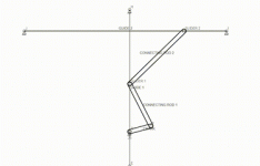
To create faster and more economical internal combustion engines, I propose to use my invention - Riyanov double-slider crank mechanism (Two-slider crank mechanism). I received 4 patents in Russia (№ 2634851), China (№ 3349271), Japan (№ 6373516) and the UK (№ 3530879) for my invention, which can be used to create more environmentally friendly and faster engines, generators or in other projects.

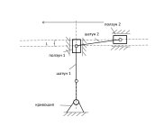
SUBSTANCE: crank double-slider mechanism includes a crank, two connecting rods and two sliders. The second connecting rod is connected to the first slider at one end, and to the second slider at the other end. The second connecting rod length is equal to the sum of the double crank length and the distance between the connection point of the second connecting rod with the first slider in the initial phase of its movement measured in the direction of the first slider travel and the longitudinal axis of the second slider.
EFFECT: ensured full turn of the crank in one stroke of the extreme slider in the chain in one direction.

The unconditional effect of the two-slider crank mechanism is overcoming the limitation in the number of revolutions per minute in the internal combustion engine for the same working stroke of the slider, which can be used in internal combustion engines requiring high speed (for example, drones (land, air, water), subcompact cars, motorcycles), as well as in electric generators based on internal combustion engines, wave electric generators.

The key predicted effects are a gain in speed, a reduction in fuel consumption, the use of fuel with a lower octane number as a result of an increase in the working stroke of the slider, simplicity of design (gears are not used to double the speed).

I propose to use internal combustion engines based on the proposed mechanism primarily in unmanned aerial vehicles.

The subject of discussion is the possibility of practical application of the proposed mechanism in internal combustion engines.

In existing internal combustion engines, the crankshaft makes half a revolution per stroke of the slider in one direction. In the proposed mechanism, it makes a full revolution per stroke of the outermost slider in the chain in one direction.Two-slider crank mechanism.jpgTwo-slider crank mechanism - animation.gif
 
Last edited:
Yep. Crank-slider mechanisms have been explored to death over millennia. There is nothing new here and the proposed application has zero advantage over what exists.

To suggest that there will be an efficiency advantage is ridiculous.
 
I think Brian said it best, paraphrasing, the novel is not necessarily better, and it is up to the proposer to demonstrate any real advantages, or at the very least persuade someone to demonstrate those advantages for him.

Amongst others https://www.swri.org/sectors/automotive will build prototypes and test them. I hazard a guess that money will be needed. Since all you have is a sketch then someone will first need to put some flesh around the bones. I'd have thought a student with a Solidworks license might be a first port of call, as a way of cheaply establishing whether there is a feasible architecture that doesn't resemble a stationary Victorian era steam engine (ie open crankcase, fumes everywhere).
 
I will try to answer specific questions if the answer has not already been given in the comments above. Comments like "this will never work, because if it worked, it would have been used long ago" or unsubstantiated accusations and insults I will leave unanswered. I hope that on an engineering forum users have critical thinking and are able to independently form their own opinion.
Nevertheless, thanks to all adequate commenters for their answers. That is why I posted here so that those who wish can express their opinion on the proposed mechanism.
 
Last edited:
I never expressed anything about the design of the mechanism previously.

If stopped at mid-piston-stroke (crank throw at the bottom), the mechanism will bind. It will not be possible to rotate the crankshaft to get the mechanism started again.

A calculation of the mechanical advantage of the piston over the crank when the piston is in this position has an indeterminate outcome. If you try to do it numerically with an old school hand calculator, the outcome will be "Error". If I were to try to do it in a programming language back when I did such things, it would be a little more specific: "Division by zero error". These are not good things. If you try to do it with a physical experiment, you will find that force applied to the piston as it approaches mid-stroke results in extremely high forces on all linkage points if there is any resistance to crankshaft turning (i.e. output torque) at all. The practical result of the binding described above is that it will deflect the various parts, and if you try to restart it by turning the crankshaft with the piston mid-stroke (at "bottom-dead-centre"), it will simply bend the piston rod (in the up/down direction on your diagram) rather than moving the piston laterally.

A normal crankshaft and piston also has an over-centre condition at every TDC and BDC point. But, it can be taken out of the over-centre condition simply by rotating the crankshaft. Nothing binds, unless someone has assembled the engine wrongly with negative piston-to-head or piston-to-valve clearance, or such a condition exists because something broke for some other reason (e.g. broken timing belt), or a foreign object got into the cylinder.

If you have an application in which the target operating RPM range is half of what it would be with a normal crankshaft and piston, a normal crankshaft and piston and a 2:1 gear reduction is a practical solution - and it doesn't have to be 2:1, it could be whatever ratio you want it to be. That's your competition - that's what you have to be "better than".
Thanks for the detailed analysis!

Passing the dead point is a standard problem of the internal combustion engine. It is solved by using flywheels, using several cylinders, the dead points of which are separated into different positions of the output shaft.
If we imagine that the mechanism is stuck in the bottom dead point, then in the same way, turning the shaft manually, the crank, by means of the connecting rod, will begin to push the slider connected to it upward, which, by means of the second connecting rod, will set the drive slider (piston) into horizontal motion. If you mean that in this position the connecting rod will simply begin to bend the horizontal piston, then I think this problem can be solved with a bearing system. Even a small deviation will provide the necessary angle for movement.
If we talk about such a situation and the "manual" method of solving the problem, then the rotation of the shaft can be synchronized with the "manual" pushing of the horizontal slider. Also, if the direction of movement of the slider (piston) is placed at an angle to the horizon, then the junction of the crank and connecting rod in the lower position under the action of gravity and a small gap will always be shifted relative to the bottom dead center. I think there are other ways to solve this problem.

As for the alternative in the form of a gear transmission with a ratio of 2:1, the production of gears requires high precision, they also have a large mass, high rigidity. In addition, the gear ratio in gear transmissions is limited by the capabilities of the metal and production technology and has a limit. Adding the proposed mechanism to the chain of gear transmissions doubles the speed of revolutions.
 
There is no such thing as a frictionless mechanism. If this mechanism comes to a stop within a few degrees of the piston-halfway point, it WILL bind, and you will NOT get out of this bind by "turning the shaft manually" (or via starting motor).

A properly assembled conventional-layout crankshaft and connecting rod and piston mechanism does not have the problem that yours does. The engine in my motorcycle, and in my van, and in anyone else's car or truck, does not need "manual pushing of the horizontal slider" (or anything comparable) to get out of a jam. Rotating the crankshaft via starting motor is enough. Every. Single. Time. Doesn't matter in which position the crankshaft is stopped.

And yes, gears require high precision, but given that my motorcycle, and my van, and anyone else's car or truck, already have plenty of gears inside them in order to make them work, it does not appear to be a significant obstacle to overcome - it is a solved problem.
If it does not get stuck when moving, why should it get stuck when stopping and moving further? When the sliders move strictly in a certain direction, the crank has no other options except to rotate in a certain direction under the action of inertia. I have given options for passing the "dead" point as an example. Methods for overcoming it have long been developed for classic ICEs, and will also suit the proposed mechanism with minor variations. Friction is overcome by bearings and lubrication.
 
Since the respondents are far more expert and experienced than you in the design, creation, and operation of mechanisms, why do you disbelieve the advice given here?

Write up a complete proposal and send it to every engine maker in the world and see if they have any response.
 
If it does not get stuck when moving, why should it get stuck when stopping and moving further?

It WILL have all sorts of problems during operation, too. I just chose not to get into that discussion, aside from (as per previous post) mentioning that you've got an indeterminate structural situation that it will pass through twice on each and every crankshaft revolution, which will manifest itself as very high bearing loads, side-loads, and con-rod loads.
 
As far as I understand, the main complaint about the design is that the horizontal slider will exert impact loads on the vertical slider during movement and destroy its guide. The vertical slider and its guide in the diagram play an auxiliary role. They are not affected by the fuel being burned and can be designed taking into account impact overloads using durable bearings and lubrication. In addition, to reduce the impact on the vertical slider, it is possible to increase the angle between the connecting rod and the guide of the horizontal slider. But in this case, the torque is reduced many times over. Imagine a right triangle, where the hypotenuse is the upper connecting rod, and the legs are half the path of the horizontal slider and the distance between the vertical slider in the initial position from the guide of the horizontal slider. The length of the crank is equal to half the difference between the length of the hypotenuse and the length of the vertical leg (L in the diagram is the distance between the vertical slider in the initial position from the guide of the horizontal slider). This option can be used when the priority is to reduce the load on the vertical guide and increase the speed, but with a multiple decrease in torque.

Also, to reduce the lateral overloads of the vertical slider guide, shock absorbers can be placed on the outer sides of the guide.

As for the fact that at the moment there are already reliable units for internal combustion engines and there is no need to invent something new, I will not comment on this.

This post is of an introductory nature, perhaps experts with more experience than me will find it useful to know about the existence of such a mechanism.
 
Last edited:
So far, nobody is finding it useful. Keep beating the bushes.
 
I hope that on an engineering forum users have critical thinking and are able to independently form their own opinion.

Everyone here has formed their own opinion, and none of them are favorable. My opinion is that the mechanism is a novelty joke that will never be used in a production engine, ever. It's a waste of time even pretending it's a useful engine configuration. Your patent was a waste of time and money, not worth the paper it was printed on.
 
You think gears are too costly and difficult to manufacture, so to get away from gears, you create a motor with the most convoluted piston and cylinder combo that god or man has ever seen. Furthermore, you want to add some sort of shock absorbing devise INSIDE your engine block to dampen side loads.

Also, to reduce the lateral overloads of the vertical slider guide, shock absorbers can be placed on the outer sides of the guide.

And you keep saying that "Friction is overcome by bearings and lubrication" but you can't just say that fraise three times in a mirror, snap your fingers and suddenly all friction disappears. It is very much still an issue, and every additional piece you add to your assembly adds to your friction losses.
 
In the end, I propose a mechanism that doubles the crank speed with the same stroke of the working slider. A longer piston stroke allows for more complete use of the fuel consumed and the use of fuel with a lower combustion rate. This mechanism also allows for an increase in the maximum possible engine speed, which can be used for internal combustion engines of aircraft and racing cars. There may be other uses, too. For example, in electric current generators.
 
Maybe throw in some Ginsu knives?
 
I suggest you find another place to pedal this garbage, try perpetual motion and flat earth forums.
 
You think gears are too costly and difficult to manufacture, so to get away from gears, you create a motor with the most convoluted piston and cylinder combo that god or man has ever seen. Furthermore, you want to add some sort of shock absorbing devise INSIDE your engine block to dampen side loads.


And you keep saying that "Friction is overcome by bearings and lubrication" but you can't just say that fraise three times in a mirror, snap your fingers and suddenly all friction disappears. It is very much still an issue, and every additional piece you add to your assembly adds to your friction losses.
Yes, you are right. The design is new and unexplored. This is a controversial decision, the question is to what extent the benefits of using the proposed mechanism outweigh its weaknesses. That is why I posted here, hoping for comments from experts.
Thanks to several adequate forum participants for their questions. Anyone who wants to can contact me either through patent attorneys or via e-mail.
 
Benefits - nil.
Weaknesses many.
Save yourself the patent attorney fees.
 
Doubling the crank speed is of very little benefit as every practical motor vehicle has to have gear reduction from crankshaft RPM to wheel RPM. Your engine would need an even higher gear ratio reduction.

My experience with the patent office is they will grant patents with gross obvious flaws and leave it to history to determine if the patent has any value what so ever. In other words, just because the patent office put a stamp on it doesn't mean it will work.
You are right - most inventions remain on paper. But people still try. Scientific and technical progress is made from these attempts.

One of the expected effects of the proposed mechanism is fuel economy, since less fuel is required to ensure the same speed.
 

Part and Inventory Search

Sponsor