Navigation
Install the app
How to install the app on iOS
Follow along with the video below to see how to install our site as a web app on your home screen.
Note: This feature may not be available in some browsers.
More options
Style variation
-
Congratulations MintJulep on being selected by the Eng-Tips community for having the most helpful posts in the forums last week. Way to Go!
You are using an out of date browser. It may not display this or other websites correctly.
You should upgrade or use an alternative browser.
You should upgrade or use an alternative browser.
Welding on a Beam 2
- Thread starter JP20
- Start date
- Status
- Not open for further replies.
JP20 said:It doesn’t seem as if one person on this thread can answer the needed questions tbh.
Yeah, we're killing you here. Sometimes we get so bunged up in fancy theoretical fun that we forget that we're dealing with a real engineer trying to solve a real problem in an expedient way.
The sketches below show how I'd tackle this if were a real problem crossing my desk. Go forth and be profitable my friend. Expend your serious mental horsepower on some problems more worthy of it.

KootK said:Yeah, we're killing you here. Sometimes we get so bunged up in fancy theoretical fun that we forget that we're dealing with a real engineer trying to solve a real problem in an expedient way.
I might have gotten slightly side tracked with trying to explain some basic shear flow concepts, but I've been trying to give JD20 some sound and practical advice.
KootK said:Expend your serious mental horsepower on some problems more worthy of it
As someone who expends a fair amount of mental horsepower designing these types of devices to be both safe and efficient, I have to say I take some offense with this. This design is not as straight forward as it seems. This beam has a significant unbraced length at 40', and the section is built up and mono-symmetric which complicates the LTB check - and it is a lifting device so you bet your ass it will see its design loads.
KootK (from the PDF markup) said:If you want to save a little money on this, I guarantee that one channel will suffice
KootK, I have a mountain of internet-respect for you, but you are adding to a pile of bad and now dangerous advice. Have you seen the proportions of the plates and channels he is using? Plate is 1.25"x36" and the channels are C15x50. You can check my math, but I get a radius of gyration of about 2" in the weak axis. Unbraced length is 40', so kl/r is about 240...this thing can't even function as a proper compression member over 40' with two channels and you're advocating for a single channel. OP has stated he hasn't checked for LTB and doesn't know how - this isn't the time for OP to just solve this in an expedient way.
JP20 said:If I took this approach would this eliminate my unbraced length dilemma?
It helps improve the unbraced strength of the beam, but you still need to check it.
Edit: couldn’t sleep because I realized I messed up my Iy calc, and subsequent radius of gyration. Kl/r is closer to 200, but I stand by what I said.
Yup, I took op's sketch to be somewhat to scale and, therefore, the beam nowhere close to 40' long. Nobody gets it right 100% of the time. I think that the proportions that I assumed are pretty clear from my sketches. I don't see the interwebs breaking over this.
KootK, I think you get it right enough times...but you know how it is on e-tips, how often do you a reasonably proportioned sketch?
I'm not worried about the interwebs breaking - I'm worried about OP's spreader beam folding like a pretzel and hurting somebody.
JP20, I double checked the slenderness ratio of your beam and I get ry = 2.32" and a kL/r = 206 > 200 which means this beam does not have any reliable compression resistance. You've stated that you didn't check this long unbraced beam for its unbraced strength, and it is apparent you didn't take the unbraced length into account when checking the compression.
Whatever bending/compression capacities you have calculated for this beam are severely overestimated - your beam design is not safe
You are missing or misunderstanding far too many concepts here to get a quick answer from e-tips. You either need to talk to your local senior engineer and get help, or if there is no other engineer at your company, its time to admit this is out of your area expertise and get outside help.
Settingsun
Structural
I suppose you could say the same for a rectangular hollow section. How does it decide whether to use its left web or its right web?Agent666 said:Load in channel can resolve through the channel web and doesn't necessarily need to go through the plate.
Is a weld's stiffness so low that channel's web has more control over the flange tip than the plate that is welded directly to the tip? I wouldn't have thought so, unless the weld is undersized.
Flitch beams are usually made from stocky elements in the direction that matters. This channel-plate section has the slender channel flanges. I think it will make a noticeable difference (shear lag and section distortion).Agent666 said:It's fundamentally no different than making a flitch plate out of timber/steel/timber plies.
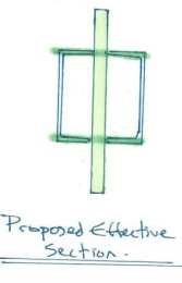
I'm interested in Canpro's effective section from 2 May @ 23:46: it amounts to an I-beam with the web extending above and below the flanges. That doesn't seem consistent with the case for no shear flow in the welds.
Settingsun
Structural
JP20 said:Can someone break down how you convert a moment to longitudinal shear?
CANPRO said:This right here makes me want to give up - I think it is has been made clear in this thread that you don't need the moment to calculate longitudinal shear.
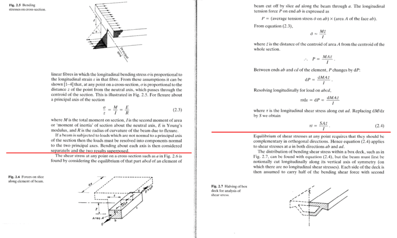
Different people think and understand differently. Whilst there is another way of calculating this, working with longitudinal stresses may be easier to understand. The explanation in the image below works in terms of longitudinal stresses right up until the end, when V=dM/dx is substituted. I've used this to help explain this to other engineers in the past when they just couldn't grasp the V*Q/(I*t) method. Then they see the physical meaning of Q.
Settingsun
Structural
I have read through and it sounds like the scheme is dead in the water in terms of lifting a load. So we're just left with the theoretical shear flow argument.
-
1
- #69
I concur with CANPRO 's slenderness calculation. kl/r>200 even though compressive loads are low it is a show stopper in my opinion.
The more I read here the more concerned I get. JP20 if this is for construction lifts I would toss the idea of building up a section from available materials as being technically infeasible and go rent a proper lift beam from someone like LGH. If you are insistent on fabricating something in the field toss this C15 idea and design a proper plate girder where design methods are straight forward and well documented.
Rigging failures are all to common in construction. Loads are hard to estimate when you consider dynamic effects as things move, high wind blowing your load around, equipment jerking due to some mechanical problem, outriggers settling, etc. etc. This is no place for a design that just meets code calculated strength.
- Thread starter
- #70
- Thread starter
- #71
JP20 k=1, I used my built up section calculator to find ry, length 40'
I am saying kl/r means you need to change direction. In my opinion the plate and C15 configuration is hard to analyze (as you can see by the length of this thread) so change your direction to a configuration that you are comfortable analyzing.
I am saying kl/r means you need to change direction. In my opinion the plate and C15 configuration is hard to analyze (as you can see by the length of this thread) so change your direction to a configuration that you are comfortable analyzing.
steveh49 said:Different people think and understand differently
I agree 100% and I love to see someone approach a problem differently than I do so I can learn. However, to suggest that you can take the moment value at any given location and turn it into a longitudinal shear is fundamentally wrong - there is no other way to look at it. I've mentioned this example 3 times now in this thread - a simply supported beam with a uniform load has its maximum shear flow demand at the supports where there is zero bending stress.
steveh49, I get that you understand this and that you're suggesting to use the bending stress to help rationalize shear flow, and from this thread it is apparent that a lot of engineers take that route. But clearly that is not effective because some of engineers responding to this thread have a fundamental misunderstanding of shear flow.
JP20 said:With that being said, what do you suggest to make the beam fully-braced?
You don't make the beam fully braced. You design for the unbraced length to ensure it has the proper capacity. Here are some key items you need to review:
[ul]
[li]Buckling of compression members[/li]
[li]Unbraced strength of bending members[/li]
[li]Lateral torsional buckling[/li]
[li]members subject to axial and bending stress (beam columns)[/li]
[/ul]
I think we've gotten quite caught up in semantics around shear flow here. Trying to put that aside, and in light of the OP's beam dimensions now being clear, I will provide some input on the design of lifting devices such as this one. I have designed several and analyzed them for more load cases than I can count. Generally, here is how I have approached these multi-hole lifting beams:
- It is often easiest to have a central plate provide the vertical shear capacity, and have it protrude above and below the lateral bracing portions of the cross-section so that you can drill holes and use those portions as lugs. That is perfectly vanilla.
- These devices are susceptible to both local and global buckling. The protruding, unbraced webs often limit the allowable stress due to their tendency to buckle locally. Because your top slings are not vertical, your lifting beam is exposed to combined compression and flexure, making it susceptible to global buckling (KL/r stuff). There's a double whammy with the flexure as those angled top slings both impose compression and additional flexure due to their eccentricity relative to the beam neutral axis.
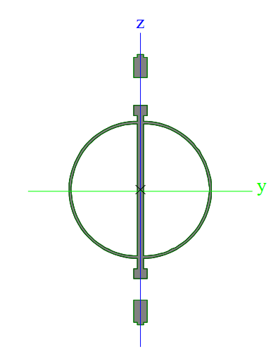
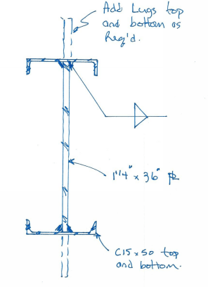
- Due to the susceptibility to global buckling, I have always designed these devices to be quite laterally stable. Use closed circular or rectangular sections to prevent LTB sensitivity. Make these portions significant so that the beam is stable, and you can also utilize them for additional flexural strength. Your central plate should not constitute the majority of your Ix. A typical cross-section (with lug holes shown) is shown below:
- I take the weak axis design quite seriously. There's potential for a suspended load to shift or induce slight lateral loads on the beam, which we know is susceptible to global buckling. I have generally designed the weak axis stiffening elements to be able to yield without splice connections or welds failing.
OP, if you haven't written us off here, you might want to reconsider your choice of lateral stiffening, and choose something that maximizes the geometry of that stiffening (such as shown in the image above).
- It is often easiest to have a central plate provide the vertical shear capacity, and have it protrude above and below the lateral bracing portions of the cross-section so that you can drill holes and use those portions as lugs. That is perfectly vanilla.
- These devices are susceptible to both local and global buckling. The protruding, unbraced webs often limit the allowable stress due to their tendency to buckle locally. Because your top slings are not vertical, your lifting beam is exposed to combined compression and flexure, making it susceptible to global buckling (KL/r stuff). There's a double whammy with the flexure as those angled top slings both impose compression and additional flexure due to their eccentricity relative to the beam neutral axis.
- Due to the susceptibility to global buckling, I have always designed these devices to be quite laterally stable. Use closed circular or rectangular sections to prevent LTB sensitivity. Make these portions significant so that the beam is stable, and you can also utilize them for additional flexural strength. Your central plate should not constitute the majority of your Ix. A typical cross-section (with lug holes shown) is shown below:

- I take the weak axis design quite seriously. There's potential for a suspended load to shift or induce slight lateral loads on the beam, which we know is susceptible to global buckling. I have generally designed the weak axis stiffening elements to be able to yield without splice connections or welds failing.
OP, if you haven't written us off here, you might want to reconsider your choice of lateral stiffening, and choose something that maximizes the geometry of that stiffening (such as shown in the image above).
Craig_H, I think you're giving JP20 excellent advice on the design procedure.
I honestly feel like I'm stuck in the twilight zone right now. The debate about shear flow was far from semantics. There was a serious misunderstanding going on here, and people were giving JP20 advice that was fundamentally incorrect. I can't bring myself to re-hash this any more, its all in the thread above.
Craig_H said:I think we've gotten quite caught up in semantics around shear flow here
I honestly feel like I'm stuck in the twilight zone right now. The debate about shear flow was far from semantics. There was a serious misunderstanding going on here, and people were giving JP20 advice that was fundamentally incorrect. I can't bring myself to re-hash this any more, its all in the thread above.
CANPRO, perhaps semantics was the wrong way to say that. I think it was a very worthwhile discussion, but perhaps would be best served by a dedicated thread. I feel a bit bad continuing to discuss the intricate details of the shear flow, but then again, it's essentially what the OP asked. On that train of thought, heck why don't I close out my own curiosity:
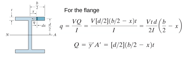
- I agree with you regarding the "effective cross section". The flanges of the channel are not going to transfer vertical shear into the channel webs, at least not much of it. The effective cross-section essentially looks like a WF section with protruding webs. I am including your sketch below for everyone's ease of access. In that case, and using your linked shear flow document, the shear flow would be given as shown below:
- Following that, the approach that I suggested early on of resolving the flexural moment in the channel into tension and compression loads that are carried by the weld seems invalid. I'll admit that deep in my gut I still feel that there's efficacy to that approach. I back-derived the approach, and it yields very near similar results. My approach almost matches the generic shear flow equation, but includes a term to account for the flexural stiffness of the flange which I believe is ignored by the general approach to shear flow. Bottom line, I think we agree, and would arrive at similar results through different approaches. Your approach is definitely more textbook.
- I agree with you regarding the "effective cross section". The flanges of the channel are not going to transfer vertical shear into the channel webs, at least not much of it. The effective cross-section essentially looks like a WF section with protruding webs. I am including your sketch below for everyone's ease of access. In that case, and using your linked shear flow document, the shear flow would be given as shown below:


- Following that, the approach that I suggested early on of resolving the flexural moment in the channel into tension and compression loads that are carried by the weld seems invalid. I'll admit that deep in my gut I still feel that there's efficacy to that approach. I back-derived the approach, and it yields very near similar results. My approach almost matches the generic shear flow equation, but includes a term to account for the flexural stiffness of the flange which I believe is ignored by the general approach to shear flow. Bottom line, I think we agree, and would arrive at similar results through different approaches. Your approach is definitely more textbook.
- Thread starter
- #77
Craig_H, I agree with your last post. I understand your gut feeling on this, shear flow comes from the change in bending stress so it isn't a stretch to associate the presence of bending stress with shear flow. On the surface, it is very intuitive to follow the approach that was incorrectly presented in this thread (using bending moment to get shear flow).
I think what you were alluding to in your statement about flange stiffness (and I think retired13 was trying to make this point earlier) is that if you look at the weld as part of the cross-section, it does indeed see stress from bending. But with shear flow, we're looking at the weld stress developed from two components trying to move relative to each other - this is the critical stress when sizing the weld, this is the load that will cause a failure plane within the weld itself (traditional weld design, weld shear at effective throat).
JP20, the channels can't easily be positioned that way - you're going to have a decent size fillet weld between your two 1.25" plates and the channel won't fit there unless you notch the top flange. If you really need to make this work with the material you have on hand, I believe this is your best shot - turn your channels into flanges and use the 1.25" plate as the web. The channels give your compression flange great Iy properties. And I think this gets us back to a shear flow condition that we can all agree on. Please review the list of topics from my previous post - I feel as though you're still missing key concepts required to make this a safe design.

JP20 said:My username says (Structural) but really I’m construction (took my PE exam in construction). And work for construction company. Maybe if I would have took the Structural exam I would know but I didn’t.
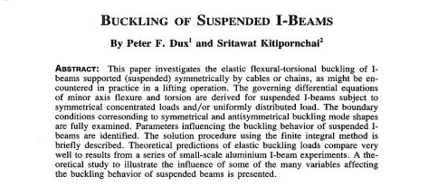
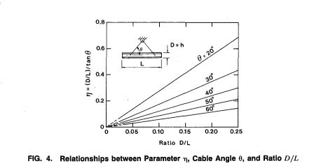
Don't feel badly, this is actually a very complex problem for most structural engineering specialists. The quite effective, yet difficult to predict nature of the LTB rotational restraint at the supports and load application points of these types of beams makes evaluation a difficult challenge. That said, it's not as though you're the first engineer to attempt this. Below are the papers that I have on the subject. Member WArose turned me on to the first and it's quite good.
- Status
- Not open for further replies.
Similar threads
- Replies
- 22
- Views
- 11K
- Question
- Replies
- 15
- Views
- 6K
- Question
- Replies
- 3
- Views
- 753
- Replies
- 8
- Views
- 14K
- Locked
- Question
- Replies
- 2
- Views
- 3K

