Navigation
Install the app
How to install the app on iOS
Follow along with the video below to see how to install our site as a web app on your home screen.
Note: This feature may not be available in some browsers.
More options
Style variation
-
Congratulations MintJulep on being selected by the Eng-Tips community for having the most helpful posts in the forums last week. Way to Go!
You are using an out of date browser. It may not display this or other websites correctly.
You should upgrade or use an alternative browser.
You should upgrade or use an alternative browser.
Welding on a Beam 2
- Thread starter JP20
- Start date
- Status
- Not open for further replies.
-
1
- #21
Johns20188
Structural
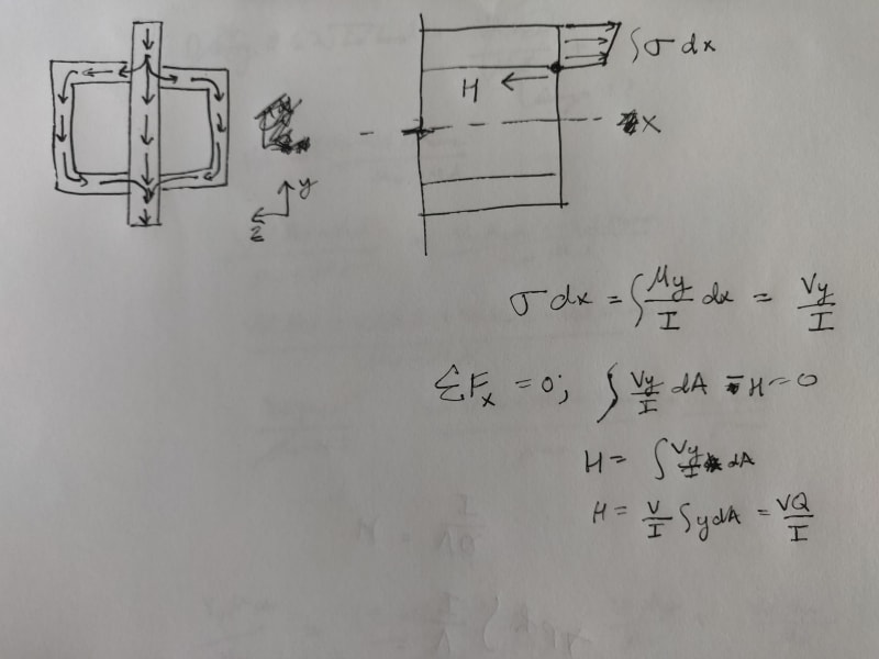
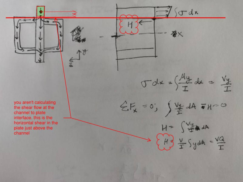
There is shear flow in strong axis bending isn't there? If it were a fully solid composite section wouldn't the shear flow sort of look like what's shown in my sketch? I think you would need to use the shear flow equation from the top protruding plate web to the welded joint. As shown on the sketch, you'll find H with the shear flow equation. I would then separate that H load into the two welds and remaining plate web based on the stiffnesses, like previously mentioned in this thread.

- Thread starter
- #24
I understand computing the shear flow at top channels that results from the max shear (V) resulting from the shear-moment diagram. Got that, we’re good.
However, I don’t understand how to apply the moment to the weld in terms of k/in.
Do I take max moment and divide by the distance from the top (or bottom) to the top (or bottom) of the channel? That would give me a kip value, so I would need to divide by another length. Would I divide by the length of beam or what?
The beam is 40’ long. Max shear is 60k. Max moment is 100 ft-k.
- Thread starter
- #26
And I take my “y” as the distance from centroid to top (or bottom) of channel?
K/in/inch of weld:
Ok say we have 10 k/in/inch of weld. I’m having a hard time correlating that. Because that’s what I was trying to do Friday and it didn’t seem right. Can you explain further please?
K/in/inch of weld:
Ok say we have 10 k/in/inch of weld. I’m having a hard time correlating that. Because that’s what I was trying to do Friday and it didn’t seem right. Can you explain further please?
Johns20188
Structural
JP20,
As I understand it (please correct me if I'm wrong), the shear flow result, H, is derived from bending stresses as you can see from the calc in the sketch above. And H is the logitudinal shear that needs to be resisted, resulting from the bending stresses, and is in units of force/unit length.
In additional to that, I believe you need to account for vertical shear in your weld strength.
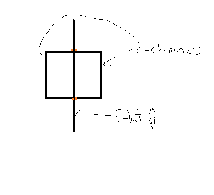
Craig, I think we agree on this part –All the centroids align, there is no shear flow in the weld. Since this is the case, you could look at this as (3) separate elements taking some portion of the total load. The channels in this case are not part of the load delivery or the support of the combined section – so if they’re carrying any vertical load from one point to another, the load must enter and exit the channel.
For arguments sake, lets say Ix plate is 2x Ix channel, so total combined Ix of the section is 4x Ix channel. Therefore each channel carries ¼ of the load, which must enter the channel somewhere near where the load is applied, similarly, the load must exit the channel near the supports.
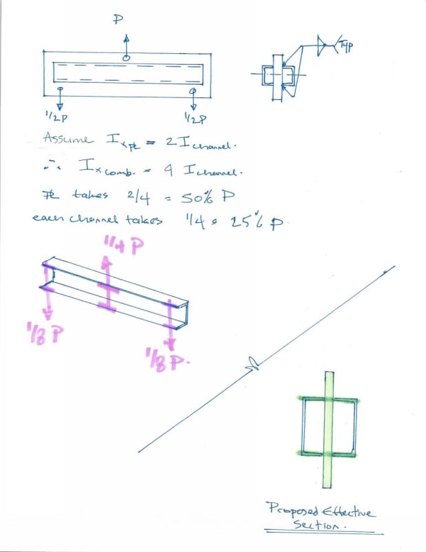
As I was thinking about how to reply to you, I gave this more thought – I don’t think the channel is fully effective. The vertical shear has to transfer in and out of the channel through the flanges (bending) and is kind of a soft load transfer – you’d need a full FEM model of the beam to confirm, but I suspect only the flange of the channel are doing much. See my proposed effective section in my sketch – for the loading/support conditions, this is what I would consider effective in strong axis bending, I would take the entire cross section as effective for weak axis section properties.
But continuity of the cross section is shear flow. You just said you agree shear flow is zero – the only purpose of the welds at that point is to make sure the vertical load is delivered to the components in proportion to the stiffness. If the channel and plate were the exact same depth and the load was bearing on the top of the plate/channel, they wouldn’t need to be welded together at all to share the load – and the stress in the channel and adjacent plate would still be the same – no weld required.
There absolutely is not. Whoever gave you the star for this has a fundamental misunderstanding of shear flow, or didn’t look at your post close enough. The work you show is for calculating the shear flow in the plate just above the channel, not in the weld between the channel and the plate.
Retired13, respectfully, you are fundamentally wrong and you’re giving JP20 incorrect advice. The bending moment in the beam does not come into play when calculating shear flow. Shear flow is not about how much bending stress is in the section, it is about how fast the bending stress in the section is being developed. Shear flow is about how much we’re adding to the bending stress, not how much is already there.
JP20, forget about the maximum moment when you’re checking shear flow. You need the maximum change in moment (location of max shear) – this is where your shear flow is greatest. You seemed to have made it clear that you understood that a few posts ago, but then you went back down the rabbit hole about bending stress with retired13 again.
For arguments sake, lets say Ix plate is 2x Ix channel, so total combined Ix of the section is 4x Ix channel. Therefore each channel carries ¼ of the load, which must enter the channel somewhere near where the load is applied, similarly, the load must exit the channel near the supports.

Craig_H said:The welds cannot transfer much vertical shear due to the obvious geometry of the channels.
As I was thinking about how to reply to you, I gave this more thought – I don’t think the channel is fully effective. The vertical shear has to transfer in and out of the channel through the flanges (bending) and is kind of a soft load transfer – you’d need a full FEM model of the beam to confirm, but I suspect only the flange of the channel are doing much. See my proposed effective section in my sketch – for the loading/support conditions, this is what I would consider effective in strong axis bending, I would take the entire cross section as effective for weak axis section properties.
Craig_H said:To me, in order to ensure continuity of the cross-section, the flexural stress where the web and channel meet must be the same
But continuity of the cross section is shear flow. You just said you agree shear flow is zero – the only purpose of the welds at that point is to make sure the vertical load is delivered to the components in proportion to the stiffness. If the channel and plate were the exact same depth and the load was bearing on the top of the plate/channel, they wouldn’t need to be welded together at all to share the load – and the stress in the channel and adjacent plate would still be the same – no weld required.
Johns20188 said:There is shear flow in strong axis bending isn't there?
There absolutely is not. Whoever gave you the star for this has a fundamental misunderstanding of shear flow, or didn’t look at your post close enough. The work you show is for calculating the shear flow in the plate just above the channel, not in the weld between the channel and the plate.

Retired13, respectfully, you are fundamentally wrong and you’re giving JP20 incorrect advice. The bending moment in the beam does not come into play when calculating shear flow. Shear flow is not about how much bending stress is in the section, it is about how fast the bending stress in the section is being developed. Shear flow is about how much we’re adding to the bending stress, not how much is already there.
JP20, forget about the maximum moment when you’re checking shear flow. You need the maximum change in moment (location of max shear) – this is where your shear flow is greatest. You seemed to have made it clear that you understood that a few posts ago, but then you went back down the rabbit hole about bending stress with retired13 again.
CANPRO,
Not to argue. The junction of the plate and the channel is suffering two separate actions occurred simultaneously - bending and shear.
Actually, the channels in OP's beam feel very little of the shear force, rather, the majority force comes from the push (compression), or pull (tension) due to bending stress on the channels. But still need to be designed for both forces conservatively. I think OP can judge by his own from this point on. Therefore I rest my case.
JP20,
Please ignore my suggestion on weld design for shear (made on 1 May 20 19:51). The steps shall be revised to read as follows:
Weld Design for shear
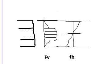
1) Find properties of the built-up section, I, Q (with respect to the area above the upper flange of the channels).
2) Compute fv = V*Q/(I*b), in which b = tp + 2*bf (of channel).
3) Design the weld for the shear force fv*Abflange
Then fv should be combined with fb as discussed above.
Please ignore my suggestion on weld design for shear (made on 1 May 20 19:51). The steps shall be revised to read as follows:
Weld Design for shear
1) Find properties of the built-up section, I, Q (with respect to the area above the upper flange of the channels).
2) Compute fv = V*Q/(I*b), in which b = tp + 2*bf (of channel).
3) Design the weld for the shear force fv*
Then fv should be combined with fb as discussed above.
Johns20188
Structural
.CANPRO said:There absolutely is not. Whoever gave you the star for this has a fundamental misunderstanding of shear flow, or didn’t look at your post close enough. The work you show is for calculating the shear flow in the plate just above the channel, not in the weld between the channel and the plate
What is the difference between the shear flow calculated in my sketch and the shear flow calculated in your book's figure 7-15 c and b?
- Thread starter
- #33
I’m now a little confused. It seems 3+ have differing opinions on how the load is transferred.
The plate itself is fine to take the entire bending moment (1.25”x36” plate) so I’m not too worried about the bending moment in the steel.
I specifically want to know what the welds are going to take load-wise.
I presume it will take shear flow from the max shear and the shear flow due to the max moment. This has to be completed tomorrow and built Monday. Need clarifications stat lol.
My username says (Structural) but really I’m construction (took my PE exam in construction). And work for construction company. Maybe if I would have took the Structural exam I would know but I didn’t.
The channels will feel stress only when bend to shape, that needs to conform to the deflection of the plate they are connected to. Nearly 100% shear force will be resisted by the middle plate. You shall have a structural engineer review your design. Hope it is not too late.
- Thread starter
- #35
Hi JP20
I was wondering why you cannot redesign the lifting beam to a more convenient shape which would allow an easier analysis of the welds? For instance my sketch attached
“Do not worry about your problems with mathematics, I assure you mine are far greater.” Albert Einstein
I was wondering why you cannot redesign the lifting beam to a more convenient shape which would allow an easier analysis of the welds? For instance my sketch attached
“Do not worry about your problems with mathematics, I assure you mine are far greater.” Albert Einstein
The bending moment in the built-up/composite beam does not come into play when calculating shear flow. To suggest otherwise is fundamentally incorrect. Jp20, read CANPRO's posts again.
The longitudinal stress in the plate and the channel either side of the weld is constant under flexure (strain is linear with depth). There is no differential stress going on that suggests a longitudinal force is being transferred along the weld due to bending in this type of symmetric arrangement.
The longitudinal stress in the plate and the channel either side of the weld is constant under flexure (strain is linear with depth). There is no differential stress going on that suggests a longitudinal force is being transferred along the weld due to bending in this type of symmetric arrangement.
Settingsun
Structural
Agent, my turn to be wrong or misunderstanding you. Apply your argument to a typical 3-plate I-girder where there is shear flow in the welds to create the composite section. The stress at the top of the web is the same as at the bottom of the top flange. It's not the stresses at a single section; it's difference in stresses at sections separated by a short (infinitesimal) distance along the beam that result in the weld stress.
I think shear lag means the central plate acts as the web for half of the flange width of the channels (or maybe more given the load application). It's better placed geometrically than the channel webs.
Edit: This forum need a serif font so "I girder" looks like an I girder!
I think shear lag means the central plate acts as the web for half of the flange width of the channels (or maybe more given the load application). It's better placed geometrically than the channel webs.
Edit: This forum need a serif font so "I girder" looks like an I girder!
- Status
- Not open for further replies.
Similar threads
- Replies
- 22
- Views
- 11K
- Question
- Replies
- 15
- Views
- 6K
- Question
- Replies
- 3
- Views
- 753
- Replies
- 8
- Views
- 14K
- Locked
- Question
- Replies
- 2
- Views
- 3K

