Continue to Site

Eng-Tips is the largest engineering community on the Internet

Intelligent Work Forums for Engineering Professionals

  • Congratulations KootK on being selected by the Eng-Tips community for having the most helpful posts in the forums last week. Way to Go!

Welding on a Beam 2

Status
Not open for further replies.

JP20

Structural
Apr 7, 2020
41
I have the below scenario: How do I resolve the force being applied to the welds given a max shear and a max moment (developed from shear-moment diagram).
The orange dots represent locations of the fillet welds. Channels are 15" deep. plate is 36" deep.
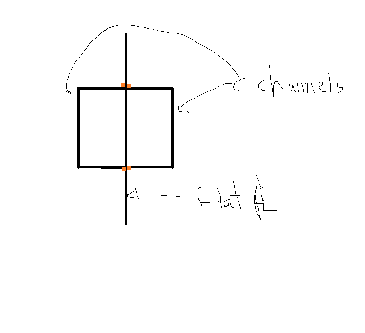
weld_ex._vtt5pe.png
 
Replies continue below

Recommended for you

I read through this morning and as I understand JP20 situation max M=100 kip-ft, plate is 36x1.25 and C15 channels (unknown size) and length 40'. I saw a comment the plate would take the load. I decided to check this using AISC section F11 (shockingly straightforward for AISC). I come up with allowable bending 804 kip-in - vs 1,200 kip-in applied. I assume unbraced length 40'. I could be wrong on the calc so please verify for yourself. Note I am using AISC ASD method with Cb=1.

I would strongly encourage you to revisit the assumption the plate will take the load.

If the plate will take the load than the C15's are your suspenders and belt - so the weld size is not as critical. However if the plate will not take the load than the C15's are critical and weld size is critical. As several people have pointed out this is a non-standard section and opinions are going to vary on the right approach. Personally I am more concerned about overall weak axis buckling (whole thing folds up like a potato chip) and buckling of the outside edges in compression.

 
ldeem,

The channels are C15x50 and the plate is considered continuously braced because the weld will be continuous and the flanges of the channels (turned around) will be resisting any out of plane bending that may occur due to the low axial load induced from the top two corner attachment points. The max moment is actually more near 80ft-k .

There will not be any loads applied in the weak axis direction.
 
JP20

I think there are several ways to look at this and each method has its merits. You will probably need to consider each method and take the most conservative approach.

So back to the stability/bracing - The two C15's will form a box section which will be good in torsion so will resist the LTB of the plate (twisting of the section). However I am not sure how you would go about proving the two C15's will provide the needed bracing to assume the plate is fully braced. An alternative would be to consider the two C15's as a box section and check that for the full 40' unbraced length. AISC-05 notes long box sections can fail in LTB but they don't give equations since deflection would normally control. That is true for buildings but your case is unique so if you go this path you should check LTB of the box shape. There are lots of long span box sections used in crane girders so this would be a good place to start. CMAA or AIST Technical Report 6

There have been several threads on stability bracing over the last few months which may be worthwhile to read up on.
 
How would the section ever see twisting action?
 
JP20, part of the requirements for stability bracing is that it resists the section twisting. You see this when looking at stability bracing points on a long beam. A full depth stiffener with a brace at the mid-point can be considered a brace point for LTB because it keeps the beam flanges from twisting. This is my understanding however I am not an expert in stability bracing requirements.

In your case for the plate only to carry the load you have to assume some amount of lateral stability bracing. In other words taking the full 40' length does not work. So the question is do the two C15's provide the lateral stability bracing to justify using some length less than 40'. In a way I can see that working because the two C15's form a box and therefore at torsionaly rigid, On the other hand I have never designed a beam that needed stability bracing and that I used members welded along the length of the beam like this. In my experience the closest I have come to something like this is having two trusses parallel to each other and I assume the chords are braced at each point where there are cross connecting members.

If it were me and because I don't know if the two C15's provide enough stability bracing I would look for another analysis method (or change the plate so it will work). The closest I can think of are crane box girders and do the analysis using the two C15's as a box girder spanning 40'. If this works it leads to the question of how to weld the C15's to the plate and satisfy the analysis assumptions made. Also you need to satisfy the load transfer from the plate to the box girder.

You have a really tricky problem on your hands here. It's good you are reaching out for opinions on this form but that is no substitute for having a peer review. Hopefully you have someone in your office or can hire a consultant familiar with your company to do a peer review of your calculations and drawings. You might also want to consider doing a weight test on this to be sure it will work.
 
Agent666 said:
The bending moment in the built-up/composite beam does not come into play when calculating shear flow. To suggest otherwise is fundamentally incorrect. Jp20, read CANPRO's posts again.

The longitudinal stress in the plate and the channel either side of the weld is constant under flexure (strain is linear with depth). There is no differential stress going on that suggests a longitudinal force is being transferred along the weld due to bending in this type of symmetric arrangement.

Longitudinal shear/shear flow IS the result of differential bendinging stress over an infinitesimally small length along the longitudinal length of the beam. The bending tensile and compressive stresses on the cross section cause there to be internal longitudinal shear stress to resist them (otherwise how does the beam section stay together?). Shear flow is the sum of the longitudinal shear stresses resulting from the bending stresses. It doesn't matter that there's no differential bending stress along the flange, there's still shear flow since there is still bending stresses (there's still shear flow in the flange of an I beam even though the flange bending stress is constant along the flange).
 
Weldment is a 3D element, thus subjects to stresses in all three orthogonal directions. The weld design stress/force is the vector sum of all stresses/forces.

f_vz9lif.png
 
Can someone break down how you convert a moment to longitudinal shear?
 
JP20 said:
I want to be super confident.

Rightly so. For repeat use of a lifting device, someone has suggested "peer review" and "load test", that are essential for your success.
 
Agent666, thank you for being another voice of reason in this thread.

Johns20188 said:
What is the difference between the shear flow calculated in my sketch and the shear flow calculated in your book's figure 7-15 c and b?

We're talking about the shear flow between the channel and the plate - your calculations were for shear flow between two portions of the plate...completely different plane, you're at the wrong location.

Johns20188 said:
It doesn't matter that there's no differential bending stress along the flange, there's still shear flow since there is still bending stresses (there's still shear flow in the flange of an I beam even though the flange bending stress is constant along the flange).

I agree with this, but we're not talking about a beam section made of 3 plates with offset centroids, we're talking a plate and 2 channels all aligned. It makes a difference.

Say for example you had two beams - one is solid 6"x6" steel and the other is a collection of 6 plates 1"x6" stacked vertically side by side but not welded together. If the plates are loaded on the top edge and bearing on the bottom edge, both beams will have the exact same strong axis bending properties and the exact same stress profile, there is no weld required for the loose collection of plates to behave the same as the solid square beam (because their centroids all align). If the loose plates were stacked horizontally (offset centroids), then you would now require a weld between layers of plate to achieve the same properties.

JP20 said:
My username says (Structural) but really I’m construction (took my PE exam in construction). And work for construction company. Maybe if I would have took the Structural exam I would know but I didn’t.

I want to be super confident.

This might not be the advice you want, but its the advice you need - you're in over your head with this one. And there is nothing wrong with admitting that. You aren't going to learn this enough to be confident in your design by Monday. And frankly, you've been given questionable advice here so if this is your last resort I think its time to ask for help (in person). The use of continuous 5/8" fillet welds is far more than you need to fully engage the channels - if you don't have an automated welding process you'll probably have the rest of the week to figure this out while they make 4 - 40' long 5/8" fillet welds. With that said, I'm happy to help you sort through some of the technical issues.

JP20 said:
Can someone break down how you convert a moment to longitudinal shear?

This right here makes me want to give up - I think it is has been made clear in this thread that you don't need the moment to calculate longitudinal shear. The moment does not develop longitudinal shear - it is the change in moment (shear) that creates longitudinal shear. Johns20188 explained it best when he said "Longitudinal shear/shear flow IS the result of differential bendinging stress over an infinitesimally small length along the longitudinal length of the beam" - it is the change in bending stress from point along the beam length to another. That is the change in bending moment, which is shear - it is not the bending moment.

Based on your plate size and channel size, the channels are only taking about 6% of the load each so they're really only helping with lateral stability properties - I think you know that. How are you checking the unbraced strength of this section? You have a very flimsy compression flange (just the bit of vertical plate) and I doubt it has much capacity over 40' unbraced length. You need to make sure your built-up section actually works before you worry about how to weld it together.

 
I am going to put a horizontally-orientated plate (between holes) on either side of the flat plate that protrudes above the channels.

It doesn’t seem as if one person on this thread can answer the needed questions tbh.
 
JP20, what question has gone unanswered? I'm not confident you know what questions you should be asking. Shear flow calculation is straight-forward and can be found in your college mechanics of materials book.

If you're welding additional plates near the top of the beam your channels are doing even less. How are you checking the unbraced strength of this beam? It is a mono-symmetric section and that check isn't exactly straight-forward.
 
Canpro, I’m not and I don’t know how to tackle that. Do you know how?
 
JP20, where are you practicing? CSA S16-14 (canadian steel code) has a nice procedure for mono-symmetric sections (cl 13.6), but I believe this only applies to I or T shape sections - there is good reason for this, you're going to want a horizontal compression flange to get you any sort of strength of 40'. I'm sure AISC has a similar procedure.

Your sketch in the other thread showed your slings inclined which will induce significant compression in your beam, has that been considered?
 
USA. Yes they induce 12.5k max in axial compression. I checked this incorporating area of section and it yielded a KSI below the allowed (computed from the formula provided by BTH)
 
steveh49 said:
Agent, my turn to be wrong or misunderstanding you. Apply your argument to a typical 3-plate I-girder where there is shear flow in the welds to create the composite section. The stress at the top of the web is the same as at the bottom of the top flange. It's not the stresses at a single section; it's difference in stresses at sections separated by a short (infinitesimal) distance along the beam that result in the weld stress.

I think shear lag means the central plate acts as the web for half of the flange width of the channels (or maybe more given the load application). It's better placed geometrically than the channel webs.

Edit: This forum need a serif font so "I girder" looks like an I girder!


I agree it's the difference in moment between two points that causes the shear flow. Another way of expressing the change in moment along the length is by saying V ∝ dM/dx......... i.e. the change in moment is proportional to the shear. We know shear flow is proportional to the shear flow. Nothing to do with longitudinal stresses derived from bending in a beam as some people were suggesting.

With an I girder, it fundamentally a different beast to what is being proposed here. The compression force in the top flange (say) has to transfer across the weld to resolve with the tension force in the bottom flange. For the symmetrical section about the centroid proposed, this is not the case. Load in channel can resolve through the channel web and doesn't necessarily need to go through the plate. There are effectively two sections placed beside one another constrained to the same deformation. I believe as others have said that if the centroids are all aligned for the different bits of steel. Then there is no shear flow.

I did some more thinking on this while I was sleeping which can be dangerous. What you have got is three bits of steel constrained to the same deformation with centroids aligned. With all the load being introduced via the plate to the system. One way to think about this scenario is that the loads are shared based on relative stiffness, work out the relative stiffness and you know the loads going between each member, size the welds for this vertical force. You have the added complication of getting the loads out at the ends of the channels.

It's fundamentally no different than making a flitch plate out of timber/steel/timber plies. Provided that the centroids are aligned, there is no shear flow. It is simply some members with dissimilar stiffness sharing a common load. Once you know the stiffness and how the loads are transferring between members and introduced to the members you can design fixings between the plies to carry the proportion of the load required to each member and follow the loadpath required for equilibrium
 
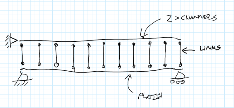
If you had to build some sort of model to represent what is going on regarding the vertical load transfer perhaps you could do something like this. With pin ended links constraining the two members to the same deformation under whatever loading you were applying. Load in these links is going to give you an indication of the vertical load transfer between the elements. This vertical load transfer is what you should be designing the welds for in my view.

Annotation_2020-05-04_124904_qe8i3o.png
 
Agent666, I mentioned the concept of treating it as 3 separate sections and splitting the load based on the the stiffness - but you’re transferring the vertical shear in the channel web to and from the plate via flange bending, so I wasn’t sure how effective this would be, feels like that load transfer might be a bit soft to say its fully effective. In terms of the model you proposed, your links wouldn’t be rigid (channel flange bending) and the load would only be applied to the plate. The pin support on the channel would be a vertical roller...only the plate is supported/loaded.
 
I am wondering if introducing 1/2” horizontal stiffeners will effectively brace the “top flange) which is the flat plate.

Also wondering if I could solve a lot of my problems by moving the plate down to be flush with the top flanges of the channels therefore I have a good compression flange. Then I could weld three eyelets on top of the plate. Although I would then have an excess amount of plate below. But that’s in tension so not much to worry about I suppose. Am i thinking right?

If I took this approach would this eliminate my unbraced length dilemma?
 
JP20,

After further review, I've to admit I made a mistake to include bending in the consideration. The weld should be designed for the shear flow at the flange-plate junction. Sorry having to misled you, and waste your precious time.

 
Status
Not open for further replies.

Part and Inventory Search

Sponsor