Eng-Tips is the largest engineering community on the Internet

Intelligent Work Forums for Engineering Professionals

Wide flange with stiffener plates against Torsion? 8

Status
Not open for further replies.

planc

Structural
Mar 3, 2022
64
0
0
CA
Ibeam_with_plates_uvcggu.jpg


can putting such stiffener plates inside the web and flange (illustrated above) produce restrain against torsion? What is the formula for the spacing of the plates?
 
Replies continue below

Recommended for you

I'm not sure how many people know this but, despite our long standing prohibition on student problems here, we now have a dedicated student forum: Link. It's working well I believe. I'm rarely interested in non-practitioner work so I just don't go there. Problem solved.

This is a bit different from a liability perspective but there may still be room for maneuvering. I never put much stock in the liability concern anyhow. I just can't see a judge blaming the supplier of online advice for the actions of some nut ball who got his engineering advice online, for free, anonymously. I still believe in some semblance or reason & order in the world.
 
chb_done_glmjf9.jpg


cbh_to_ibeam_ggazxe.jpg

\\\These 6" 700psi nonbearing walls are almost done. But I need to put parapet on top of the I shaped Beam. The ibeam longest span is 5.5 meters. Can parapet be supported above it or do i have to close up the flange with plates to increaes torsion resistance. I don't like my parapet to twist during lateral movement. The original designer said it was designed to resist torsion. But BARetired didn't agree. Would getting plates to close them of is just for extra precaution. Then no problem implementing it. I am an engineer and owner of the building.


w8x21_ur2kzk.jpg


What is the uniform load at 18 feet span (5.5 meters). Is it really 70.1 kN? Since my parapet load would only be 2.73 kN.Much less than 10%, the wall won't rotate and fall by becoming horizontal?
My designer can't give me further details as he doesn't know how to manually computer. He just got them from Etabs and can't say further. I'm just verifying the concepts and torsion performance of the 2.73kN/meter parapet above it. Come on. Help me one last time. Compute the 2.73kN/m wall along 5.5 meters (18) feet between support. Can small vibration in flood or moderate seismic sway it enough to initiate moment magnification that would shred the entire w8x21? Thanks.
 
KootK - don't forget about 'stripez'. He hasn't been around for a while, but is assuredly the same person as pixy. And judging from the pictures of the building in these threads:

thread507-479858
thread507-493304
thread507-493564

I'm 98% certain all three are the same person.

Pro-tip: if your local engineers are so bad you need to get anonymous engineering direction from strangers on the internet, don't invest in buildings in your home country!
 
I just came here to comment on the masonry work, good thing there are no architects looking at these pictures, they would be screaming at the computer right now! Also, why is the vertical reinforcing in the vertical mortar joints between the blocks or is this a trick on my eyes?
 
Usually spacing between vertical rebars are 24" (600mm) and every 3 layers and they use 10mm.

I bought 12mm and told the masons to use spacing in between middle of each block. He did that right on the first layer but then on the second layer, that's the problem where the rebar is in between the blocks. He was supposed to be an expert mason, but I wonder why he didn't put them at the sides so all cells can be filled up.

Had I shown a picture when the wall was much lowered. And your eagle eye saw it. We could have corrected it. Our structural engineers (mostly) never visited any of their projects. They don't care how you connect them.

But then, in the literature like in the following, people used bars in between blocks in alternate layers.

chb_bars_sjodga.jpg


Could the purpose so the wall shouldn't be too much reinforced turning it into a shear wall? Maybe there is a purpose? or just outright stupidity?

So I can tell the mason how to lay it properly, especially in the parapet.

So the span of the w8x21 is 5.5 meter without any brace, the original designed said we can put parapet and the torsion was designed for it. But these are newly graduates civil engineers who popular the department senior stuff. And the head doesn't even know meaning of stress vs stain. So please tell me whether the bars should be move sideways so it engages every block. Even if it would strengthen the wall so much it can turn them into shear wall? It's just non-bearing wall now.
 
The masons cut the middle and inserted it. He said they do it in all buildings.

cut_mid_chb_kspznc.jpg


ibeam_sides_dhzu3o.jpg


Anyway. On top of the masonry above is a a 5.5 meter (18 feet) span W8x21 beam (unbraced at middle or not torsionally restraint at middle) and will carry 4 to 6 inches of 39" high parapet or load of 273kN/meter or 0.187 kip/foot or 187 lbs per foot. (The shiny metal besides the I-beam is thin aluminum gutter).

The span of the W8x21 between edge of column is 5.5 meters or 18 feet. All the structural engineers I asked here only based it on software. They said the I-beam can support the parapet. And they can't give me any manual computation. Can you please enter the span and w8x21 in your software and get the maximum load capacity and torsion? I'm still learning to manually compute for it Please do it asap before this thread is entirely deleted. I'm a civil engineer just checking the design and learning but it seems some mods are delete thread trigger happy.
 

First time I've seen that done...

Rather than think climate change and the corona virus as science, think of it as the wrath of God. Do you feel any better?

-Dik
 
pixy said:
All the structural engineers I asked here only based it on software. They said the I-beam can support the parapet. And they can't give me any manual computation.

Have you tried offering them money?
 
Have you tried offering them money?

They were the designer of the building but on many occasions their skills were doubtful. I'll give example.

1. They design sorely special moments frames. We almost never used shear walls. But when I confronted them years ago why the shear resistance of the concrete beam was less than a certain value (that is, by ignoring Vc and relying entire on rebar stirrups Vs). They were perplexed how a concrete beam of many closedly spaced stirrups were still not sufficient. They didn't know from their own excel file that it was basing it entirely on Vs and ignoring any Vc (shear capacity from concrete). So they designed carbon fiber wrapping to increase section capacity similar to Vs only. So from this, they already made mistakes.

They rarely checked for plastic moment strength and rarely used Vs only because they used so called standard spacing of 4" of 0.25" diameter stirrups in small beams. So they forgot to check.

If I had a chance to go back in time. I'd design all beams shear capacity specially near support to be based on Vs only, and ignoring Vc.

2. They can't understand pure epoxy stress and strain. So whenever they have clients with honeycombs even in lower columns that is a meter high. They told them to inject with pure liquid epoxy. The strain is so dissimilar that it won't work as they thought it would. The company head told me pure liquid epoxy can bind the parts and not grouted epoxy which is what should be put. They can't understand my explanation of stress and strain. And they are designers of 50 storey buildings. Supposed one of the best structural firms in the country.

With that experience, how can you trust them again. With no competent ones. I need to double check everything just to be sure. Hence just asking tips from the worlds best structural engineers, you guys.

Btw.. if the lower flange is bearing on the 700 psi masonry blocks wall and the wall is restraining the lower flange from any torsion. Can the top flange of an Ibeam or I shaped steal beam and its web can have independent torsion that is as strong as that of an I-beam with lower flange that is not restrained.. or more diminished? This is what I'm trying to learn today. I understand the loading of the Ibeam may transfer to the wall.
 
I know of no such reference and, given how specialized the application is, I'd be surprised if anything were available in print.

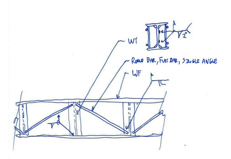
If you're going the truss route, then I feel that the first step is figuring out how to construct and detail that. I've presented one option below.

As for the design of the trussed beam, I would be inclined to model the torsional properties of the assembly as a box or space truss, with the flanges represented by trusses having equivalent shear characteristics to the solid flange. As you rightly anticipated, this design exercise will be quite a bit more involved that just doing the basic checks on a built up HSS.


flange_torsion_retrofit_vx9xyg.png


Bad news. Our steel company refused to cut the 8mm 4x8 feet plate into 8 feet by 7 inches long we are planning to get. And there is only one company selling such 4x8 feet plate. They said their machine not capable of cutting them but capable only for bigger cuts like baseplates. Is this possible? I think they just want to avoid the hassle.

Guys. What is meant by WT above? I know WF means Wide Flange. And why is there what appears to be longitudinal rebars in the side view?

I have a friend who is full time structural engineer who design and build houses. I'll let him study this thread and see if he can design it. Of course. I'll not design it myself, but as a fellow engineer just need to know if he is doing it right. This very moment, he is reading the thread and learning too. If he can't do it and no one else can reachable by bus, then truly need international assistance for something no one in my place can do. If this is the case. Can one of you guys just design the flange with trusses and waive all liability. Better yet, make the wide flanges with side trusses part of software and public domain. Include this in ACI code since we literally copied the ACI word for word (even down to misspelling).
 
wf_x4fcmp.jpg


I found out WT comes from hybrid of Tee Beam split from Wide Flange beam.

This is very rare to find, and if our steel company won't cut 8mm 4x8 feet plate. The more they would not be willing to cut an Wide flange into half and then pieces!

Creative team,

What steel sections can you think of easily available that can be used in the following exact I beam size, W8x21?

wf_w8x21_tx2pnm.jpg


There is free space of about 2.5" to the web of the w8x21 (8.27"-0.25"). The easiest I can think of is welding two angle bars together but the thickness of our angles is only 3mm or 1/8". If you have thought of one, please suggest something easier so our designers can put it in the drawing board as we are literally running out of idea.

It's just for redundant or extra torsion retrofit. And I won't bother you next time again. Thanks!
 
KootK said:
I know of no such reference and, given how specialized the application is, I'd be surprised if anything were available in print

It's done in steel trough bridges (steel U beam with concrete deck). The top is 'closed' with a horizontal truss for the temporary case before the deck is poured. I can't find the reference used at a (very) former employer, but FHWA/TX-07/0-4307-1 appears,at a glance, to cover it (section 3.2).

I think similar would apply to stiffeners perpendicular to the web, just with reduced horizontal dimension of the equivalent box.

Edit: I suppose I could provide a link...

 
Thanks for that steveh49. I get a lot of mileage out of your familiarity with nifty resources from the bridge world. I'm even one of a very small number of people who owns a copy of the Kollbrunner and Basler book. Fun.

@OP: I feel that the trussing idea needs to be abandoned given the size of your beam. It's just not viable for something as small as a W8x21. I was imagining something much larger when I proposed my trussing scheme.

C01_qvg9yw.png
 
If you’re adding parapet (and wall below) why the need to cantilever off the open section? Why not detail the parapet to avoid loading the beam in torsion?
 
planc said:
What would happen if you used trusses on the sides made of angle bars instead of whole one piece plate? It's very difficult to transport whole plates.

I have used the following reference before. The whole book is obviously too big to attach but I have extracted the relevant pages (ignore my handwritten notes).
Kollbrunner and Baslar (1969), Torsion in Structures - An Engineering Approach
I think KootK's screenshot make reference to this.

 
Kootk
@OP: I feel that the trussing idea needs to be abandoned given the size of your beam. It's just not viable for something as small as a W8x21. I was imagining something much larger when I proposed my trussing scheme.

So given the w8x21 is very small, and has poor torsion, how do you strengthen its torsion if not for plates or trusses. You are saying the plates are only viable solution?

Perhaps we can get the biggest flat bar and just weld every 3" of them with thickness of 1/8"?


Tomfh
If you’re adding parapet (and wall below) why the need to cantilever off the open section? Why not detail the parapet to avoid loading the beam in torsion?

What do you mean cantilever off the open section (or ibeam)? It's not cantilever or resting on wall below. The I-beam is between column 5.5 meters span anchored on top of baseplates. And the baseplates are about to be capped (that is, 4 new 16mm baseplates welded to original top baseplate to form a formidable steel cap and this is for each column) to increase shear resistance from poor original anchor bolts. Below in lower left and right are the baseplates for the steel caps delivered.

baseplates__sntytd.jpg


And what you mean about detailing the parapet to avoid loading it in torsion? It will be put in the center of the I-beam and not eccentric. The torsions will only come if there is severe seismic shaking of the building or unanticipated resonant effect where the ground shake would be in resonance of the building, then the 39" high parapet can move back and forth like pendulum for many minutes. And the w8x21 may twist back and forth. If this is not what you have in mind. What you mean about detailing the parapet to avoid loading it in torsion? LIke what for example? The ends of the parapet will be connected to steel extended from column.
 
Status
Not open for further replies.
Back
Top