Continue to Site

Eng-Tips is the largest engineering community on the Internet

Intelligent Work Forums for Engineering Professionals

  • Congratulations waross on being selected by the Eng-Tips community for having the most helpful posts in the forums last week. Way to Go!

Wood open roof 2

Status
Not open for further replies.

milkshakelake

Structural
Jul 15, 2013
1,109
Client wants an open gable roof. I don't like to do it generally because of lateral thrust; I'm more comfortable with having horizontal attic joists. Are there any references for how to design something like this? I was considering having some horizontal timber beams at like 8'-0" on center to deal with the thrust, beyond the window so the structure wouldn't obscure the facade.
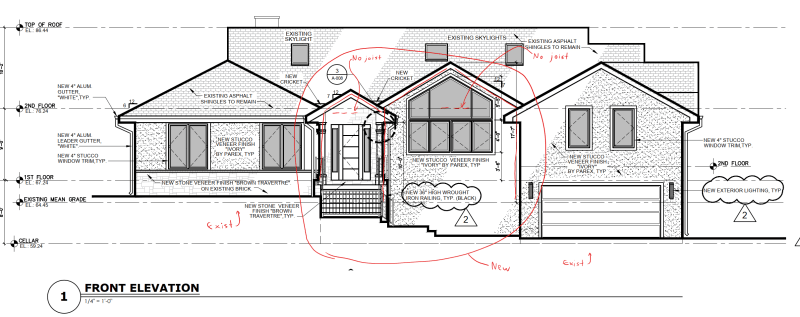
Screenshot_2023-11-17_103647_fe1eka.png
 
Replies continue below

Recommended for you

Could do periodically-spaced bent steel frames within the roof cavity
 
I've worked out eave beams before, designed for bi-axial bending from gravity and thrust. They're usually timbers, with decent "b" dimensions, and not too long of spans.
 
@alt0 I get what you're coming from, but steel is expensive. Would like to keep it to wood if possible.

@kissymoose Good idea. I'm guessing the eave beam can be pinned at the ends of the walls to transfer minor axis reaction from thrust.
 
I would also try to use a thrust beam, or rely on the adjacent roof diaphragms to provide thrust resistance.
 
@Eng16080 By thrust beam, you mean like horizontal timbers every 6' or 8' or so? I was thinking of that, but I like kissymoose's idea of eave beams because it gives a cleaner look. I don't want to rely on adjacent roof diaphragms because there are two open roofs next to each other. If it was just one open roof, it could work, but two next to each other introduces a bunch of pins.
 
Ill throw in a Vote for a Ridge beam and and a bent steel header. Do away with the lateral thrust problem all together. Obv, I would like to see the roof / floor plans.
 
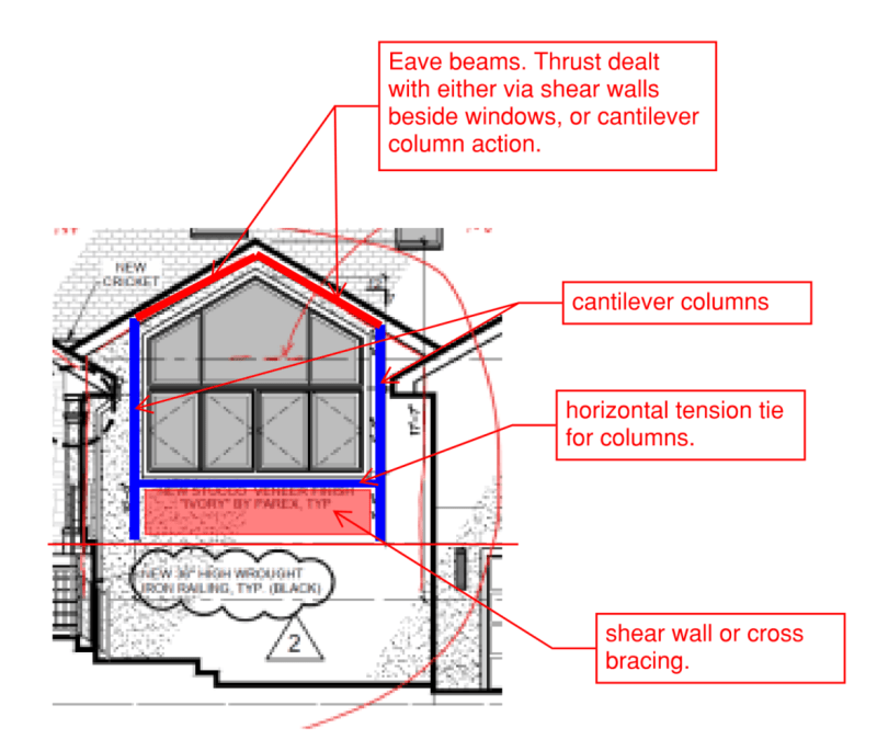
Could you create a shear wall/tension tie and bracing below the window stiff enough and have columns cantilever from the floor framing, past the top of the shearwall/tension tie and bracing
Screenshot_2023-11-17_121539_n6yrz9.png
 
milkshakelake said:
By thrust beam, you mean like horizontal timbers every 6' or 8' or so? I was thinking of that, but I like kissymoose's idea of eave beams because it gives a cleaner look.
Sorry, I was unclear. No, I meant exactly what kissymoose wrote, eave beams.

I like jayrods's idea as well. Perhaps you can design shear walls there that work for the thrust. I've used the cantilever column approach, although I usually find that steel is required for that to work.
 
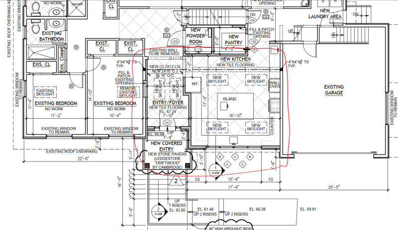
@driftLimiter You mean a steel moment frame? It costs a lot of money for the client. I'm trying to stick to wood if I can make it work. But the floor plan is below:

Screenshot_2023-11-17_140133_jytgp7.png


I hesitate to post it because all the sizes there are preliminary, done by the architect. I know someone out there will kill me for using 2 LVLs for 25' span...

@jayrod12 That's a great idea, I like it. I think engaging both the shear walls and relying on some cantilever will work.

@Eng16080 Yeah, I don't think the cantilever column will work just by itself. But combined with the shear walls, it should be enough to handle the thrust. Anyway, I've got a tiny bit of leeway because the adjacent roofs have horizontal rafters. I'm not going to factor them into the calculation, but I think they can handle about 15% to 50% of the thrust, so I have a bit of safety.
 
Not a moment frame, just a bent beam that is continuous over the ridge. Supported by columns on each end.

And Its not the steel that costs a lot of money, its framing around the large window lol.

I've had trouble getting the cantilever column to work with wood. Especially if its collecting thrust from out in the open area.
 
If the wood option doesn't work out, can reduce the amount of steel used with a bent steel flitch plate thru-bolted into some LVL rafters
 
Structural ridge and a cranked flitch or I-beam at the gable to support it.
 
What an architectural mess! Why not move the left side of the kitchen roof up to match the left side of the center roof? Then there are two walls on the sides to take the thrust. Can always put a short smaller gable over the porch area.
 
With jayrod's idea you're still going to need the eave beams to transfer the thrust into each end, else you're relying on the roof sheathing to do so. You'll also need a shear wall or tension tie element at that interior wall, and/or drag it into adjacent diaphragms. With the snow loads in my area I'd be doubtful I'd get a reasonable eave beam to span the 17' for the weak axis bending unless they're good with an exposed timber wider than the stud wall.

I'd be going the route of driftlimiter/XR250 for this one.
 
I recommend framing conventionally (2x rafters, 2x ridge board) and design the adjacent structures to take the thrust.

I am reminded by the saying I believe attributable to Abe Lincoln:
"If you call a tail a leg, how many legs does a dog have?
The answer is 4. Just because you call a tail a leg, that doesn't make it a leg."

If you use periodically placed inverted steel chevrons (HSS sections or whatever), and you did a complete 3D analytical model, you would find the axial stiffness of the rafters to be greater than the flexural stiffness of the chevrons, and therefore would still transfer axial loads to the adjacent structures.

If you use a wood ridge beam spanning to a single inverted chevron at the end, you would find the axial stiffness of the rafters greater than the flexural stiffness of the ridge beam and inverted chevron combo, and therefore would still transfer axial loads to the adjacent structures.

If you used conventional framing, you can (conservatively) take the total horizontal thrust into either adjacent structure without a 3D model and disregard the relative stiffness of the adjacent structures. This would mean you would probably end up with cantilever steel columns at the entry. On the other structure (to the right in your elevation), you would add the load (with the appropriate load combination factors) for the design of the diaphragm and shear wall. This might sound a little messy, but, in the end, you would never have to think about this problem again and I would guess, the results would not be that onerous. If the owner doesn't want to pay for cantilevered columns at the entry, tell him/her the alternative would be ceiling ties.
 
Trying to get the adjacent structure to take the thrust will likely be a detailing and construction nightmare.
Do what me and Driflimiter suggested - cranked eave beam and a structural ridge. That is the most common way to take care of this.
 
XR250 - Detailing and construction is the easiest part. Just put a sleeper down like Cal. Fill Framing.

The structural ridge is not going to alleviate the thrust. The deflection of the ridge beam will be resisted by the axial stiffness of the rafters.

I agree the way you suggest is the most common way, but it is wrong IMO because it doesn't eliminate the thrust, thus the 5 leg analogy.
 
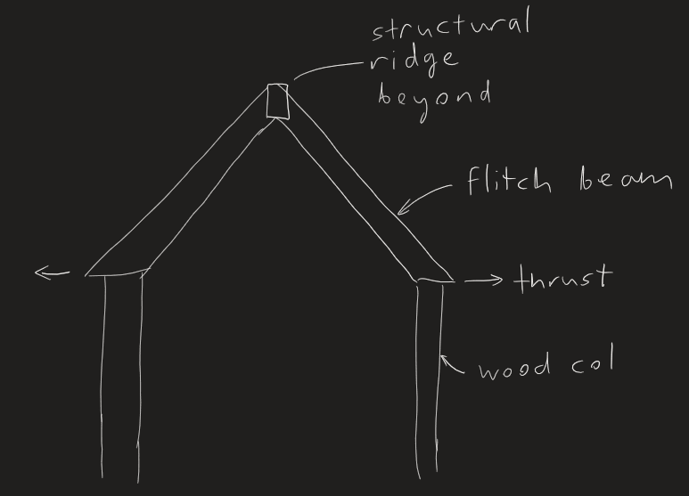
@driftLimiter @alt0 @XR250 I'm having a hard time visualizing this, and how the load path works out to resolve the thrust. Can someone send a sketch or a detail they've used in the past? I sketched what I think you're saying below. From what I see, it's putting the thrust into the wood column, which will need to be engaged by the shear wall.

Screenshot_2023-11-18_143213_mi9lms.png


@SWComposites *shrugs* If it were my own house, I think I'd like this layout. Kind of gives a symmetrical look to the kitchen.

@SE2607 That does make sense, that although I expect the diaphragm to be in a lateral beam action, a lot of the load is just going into adjacent rafters.
 
milkshakelake - I'm not sure I understand your point.
The lateral thrust will be a lateral load into the adjacent diaphragms connected to shear resisting elements). It won't go into adjacent rafters because there is nothing resisting the horizontal load. The horizontal load must come out somewhere and that "somewhere" will be lateral resisting elements.
 
Status
Not open for further replies.

Part and Inventory Search

Sponsor