Continue to Site

Eng-Tips is the largest engineering community on the Internet

Intelligent Work Forums for Engineering Professionals

  • Congratulations waross on being selected by the Eng-Tips community for having the most helpful posts in the forums last week. Way to Go!

Wood Roof - Thrust 9

Status
Not open for further replies.

Buleeek

Structural
Sep 5, 2017
98
Hi everyone,

I'm analyzing the TFEC Bulletin No. 2018-12 "Behavior of statically determinate and indeterminate rafters". If I use a collar tie (or strut) system (with no horizontal reaction at the bottom of the rafter)can I assume there will actually be NO horizontal force at the wall top plate? I know that collar ties should not be used to carry the thrust, but struts yes (located higher than top plate level in this case).

I am not sure what situation occurs in a real life. I can't assume that the rafter has no thrust at the bottom, since it is resting on the wall plate and is always notched/nailed/connected.

What do you usually do in such situation? That assumption determines a wall design and how much thrust it will carry.

Thanks,
 
Replies continue below

Recommended for you

Almost all investigations I've done on roof failures of collar ties... they are loaded in compression and have 'punched' through the roof sheathing.

Dik
 
The Engineering Guide for Wood Frame Construction (Canadian Wood Council) provides solutions for this. Includes nailing requirements. Easy to follow.
 
dik said:
Almost all investigations I've done on roof failures of collar ties... they are loaded in compression and have 'punched' through the roof sheathing.

That's interesting; I've never seen that type of failure...but this is more of a rafter tie than a collar tie. It could be loaded in compression under snow load if the deck is behaving as a rigid diaphragm spanning between end walls.

Maybe rafter ties should be designed to resist either tension or compression.

BA
 
BA,

Maybe rafter ties should be designed to resist either tension or compression.

Wasn't it done this way? I think it's a must for wind events can go either ways. (Note, I don't deal with wood design)
 
I don't believe that rafter ties are normally braced to resist compression. Their purpose is presumably to prevent the spread of bearing walls, but in many cases, as noted by oldestguy, this is not the case.

BA
 
I believe that there is a problem with the force and free body diagrams you guys are talking about.

Rafter ties need to be designed for tension. They perform in the same manner as would the lower chord member of a truss. In fact use of a rafter tie creats a mini truss, however transfer of the load in the rafter below the tie to the wall (outside of the truss formation) relies on the moment and shear carrying capacity of the rafter. Collar ties act in a similar manner, however the depth of the effective truss that they create is much shallower, hence proportional collar tie tension forces would be considerably greater (while moment in the rafter is greatly increased). The problem with your force diagrams is that they neglect the moment and shear and tension forces that the rafter must develop to carry the roof load to the wall, which is responsible for inducing a horizontally directed outward kick on the wall in addition to the normal vertical load.

“What I told you was true ... from a certain point of view.” - Obi-Wan Kenobi, "Return of the Jedi"
 
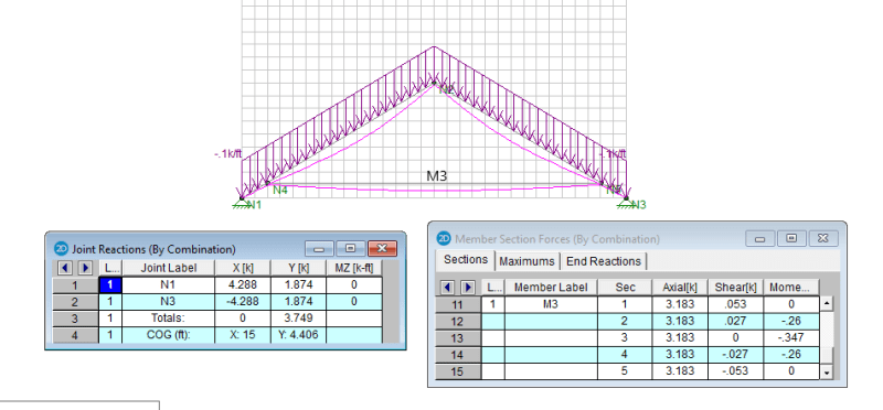
A disturbing finding, or a mistake is in making. See the simple frame analysis (by RISA) below. The scale is 3V:5H.

t_nwihnz.png
 
retired13,

You are indicating a hinge at each end, so your results cannot be right.

BA
 
BA,

Why? Isn't the rafter needs to be fastened to the wall, that will restrict vertical and horizontal movement of the tip of the rafter, thus acting as a pin support? I see the only case that will result in zero horizontal force is all loads are joint load, so the frame is acting as a pure axially loaded truss.
 
Told ya. Exactly my point. Draw it as a complete truss with the rafter tie as the bottom chord and note the tension (3000 something kips). Now in your mind, cut the rafter. That force can't just disappear. The bottom cord tension force was needed to keep the end joints from moving apart. Now, without that rafter, what will keep them from moving apart? The only thing available to resist the horizontal outward movement is the wall.

“What I told you was true ... from a certain point of view.” - Obi-Wan Kenobi, "Return of the Jedi"
 
ax1e said:
I believe that there is a problem with the force and free body diagrams you guys are talking about.

Rafter ties need to be designed for tension. They perform in the same manner as would the lower chord member of a truss. In fact use of a rafter tie creats a mini truss, however transfer of the load in the rafter below the tie to the wall (outside of the truss formation) relies on the moment and shear carrying capacity of the rafter. Collar ties act in a similar manner, however the depth of the effective truss that they create is much shallower, hence proportional collar tie tension forces would be considerably greater (while moment in the rafter is greatly increased). The problem with your force diagrams is that they neglect the moment and shear and tension forces that the rafter must develop to carry the roof load to the wall, which is responsible for inducing a horizontally directed outward kick on the wall in addition to the normal vertical load.

There may well be a problem but your comments are true only for certain assumptions.

In the absence of a ridge beam and diaphragm action of the deck, you are correct about the rafter ties. They are in tension and they tend to reduce spread of bearing walls. If there are also collar ties, they may act in compression under balanced snow load, but their main purpose is to prevent rafters from separating at the peak due to wind uplift and in that case, they will act in tension.

If there is a ridge beam capable of carrying half the roof load, rafter ties are not required, but if used, will usually be loaded in compression due to the deflection of opposing rafters.

If the deck acts like a deep beam loaded parallel to the roof slope as mentioned by oldestguy, the beam is very stiff and will reduce (but not eliminate) spread in the walls. It is not clear whether the rafter ties are loaded in tension or compression under balanced snow load because geometry and relative stiffnesses come into play. As stated earlier by KootK, engineers do not like to rely on diaphragm action of deck because it is difficult to design and inspect and may be lost if the owner penetrates the diaphragm in critical locations.

BA
 
retired13 said:
Why? Isn't the rafter needs to be fastened to the wall, that will restrict vertical and horizontal movement of the tip of the rafter, thus acting as a pin support? I see the only case that will result in zero horizontal force is all loads are joint load, so the frame is acting as a pure axially loaded truss.

A stud wall will restrict vertical, but not horizontal movement. How could it? It would have to behave as a cantilever with zero deflection. The walls must spread by the elongation of the rafter tie plus the horizontal deflection of the rafter ends.

BA
 
Perhaps you would like to explain this. There are many many rubble wall buildings near where I live, and actually one extremely old part of my own house also has rubble walls. The wall is 10m long by 5m wide and it has rafters spanning the 5m placed at 1/2m c/c without rafter ties, however there are two immense "rafter ties" placed at 3.33 m spacings, notched and keyed into the top plate running along the top of the wall. In the old uninhabited housed nearby, where the rafter ties have rotted away and were they were not replaced by tension cables, their walls indeed buldge outward in every case. None have fixed hinges, roller bearings, or slide plates of any kind. The rafters just sit on the top plate, yet the wall buldges out soon the rafter ties disappear.

“What I told you was true ... from a certain point of view.” - Obi-Wan Kenobi, "Return of the Jedi"
 
BA,

Thanks, I got the point. After horizontal restraint is released, the horizontal reaction at the tips disappeared, with the slight increase in lateral translation. The stud walls shall be flexible enough to absorb the small movement though.
 
ax1e,

Seems odd that your municipal government allows such derelict buildings to remain standing. They are clearly a danger to children playing in the vicinity.

I'm not sure how that ties in with this thread, but perhaps, if you wish to pursue it, you should start a new thread complete with photographs of the old buildings.

BA
 

In the last 50 years, I've seen over half a dozen of 'em.

Dik
 
retired13... what happens if you put one of the supports on a roller and raise the collar tie to 1/3 point?


Dik
 
Old buildings. I've got disk drives full up with them. Most not worth the pixels they're written on. I would rather concentrate on pictures of the nicer buildings.

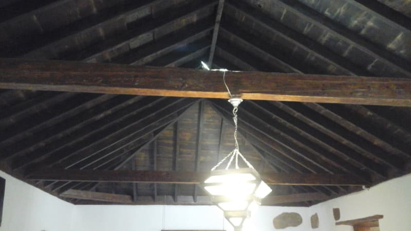
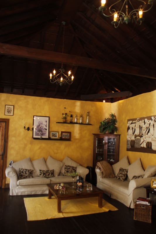
I should have thought about posting a photo of my own roof. Just took a couple. Notice the 2 long wall ties plus you can also see there also are corner ties, which I failed to mention before. All the wood is "tea", pronounced more like "tay-a". It is a type of pine and extremely dense and rot resistant. Specific gravity is nearly 1. Hard as iron and difficult to work. It quickly dulls most blades. Evven the very old, supposedly dried up stuff is full of sap that clogs saw blades in seconds. The sawdust is sticky, very messy as it sticks to my hands and shoes and the wife gets really PO if I go inside forgetting my shoes are still on. Even making a simple key chain out of it is trying. I have been meaning to attempt to measure its Young's modulus, but I have not done that yet. It is strangely fire resistant. It chars on the outside, but doesn't ever quite catch.

20200610_075935_djonnq.jpg

20200610_080117_lilgod.jpg


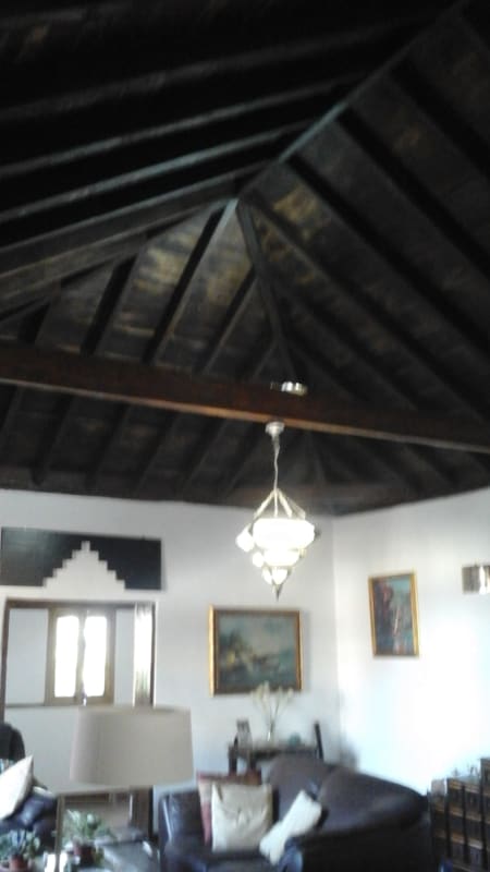
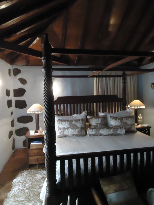
Some roofs in my friends houses demonstrating it is a wide spread, traditional construction technique.

DSC03694_isyeh2.jpg

_MG_9247_vkknb7.jpg


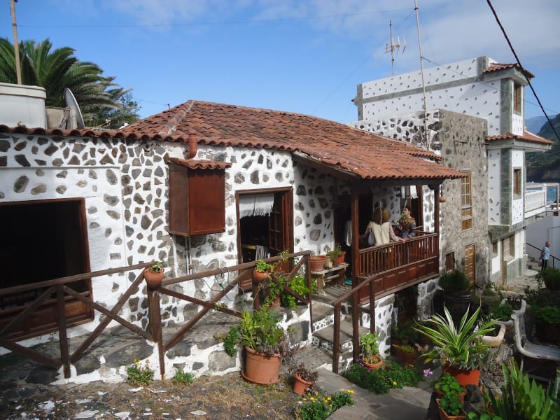
Exterior view of one of the region's typical very, very old houses.

DSC03351_vzze55.jpg


“What I told you was true ... from a certain point of view.” - Obi-Wan Kenobi, "Return of the Jedi"
 
ax1e,

Neat photos. I'm not familiar with tea wood, but, from your description, it sounds like a bear to work with. Hip roofs are generally more stable than gable roofs. The shape of the hip roof makes it act like a shell or folded plate. When the length is only slightly greater than the width, the length of ridge line approaches zero and the hip roof approaches a pyramid which is extremely stable, probably needing only corner ties.

When the length is quite a bit larger than the width, ties are used at a reasonable spacing at the top of the long walls in order to prevent them from bulging out when loaded with snow.

Of all the roof types shown below, a hip roof is one of the most stable. Rafter ties, if used, could not be precisely analyzed without including the contribution of the shell-like behaviour of the roof structure.

RoofTypes_o2pgcp.png


BA
 
Status
Not open for further replies.

Part and Inventory Search

Sponsor