Continue to Site

Eng-Tips is the largest engineering community on the Internet

Intelligent Work Forums for Engineering Professionals

  • Congratulations IDS on being selected by the Eng-Tips community for having the most helpful posts in the forums last week. Way to Go!

Translation modifier question

Status
Not open for further replies.

SeasonLee

Mechanical
Sep 15, 2008
912
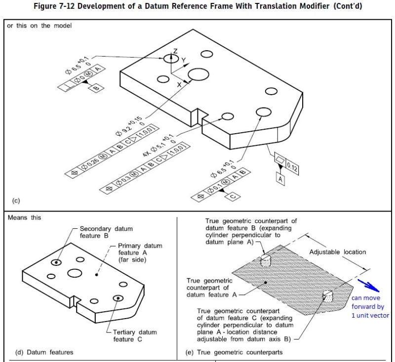
Please see Figure 7-12(c) of 2018 version as shown below.
2020-05-11_202345_nttpks.jpg


My question is : the unit vector designation [1,0,0] followed by Translation modifier means the true geometric counterpart of datum feature C can be moved by 1 unit vector on X-axis as indicated by the arrow[highlight #FCE94F](Edit: added by me)[/highlight], I can't inderstand why the translation(1) can be larger than the datum feature C position tolerance(Ø0.1).

Thanks for the help


Season
 
Replies continue below

Recommended for you

A unit vector tells the direction; the size of the motion is the unit vector component times the allowed movement, assuming the Y14.5 people have not decided to redefine how linear algebra works.

I'll wait until ASME publishes a corrected version of the 2018 version where everyone sees the same diagrams.
 
I guess I draw the short straw as my version of 2018 does not have the blue arrow nor the "can move forward by 1 unit vector" text.

Season,

Are you in the committee and the "addition" (blue arrow and text) was always the intent and how the new version of Y14.5 to look like?
Otherwise how to explain that there are multiple versions of the same standard revision on the market?

Why is shown in blue? Is this your own addition or adjustment?


greenimi said:
I guess I draw the short straw as my version of 2018 does not have the blue arrow nor the "can move forward by 1 unit vector" text.

That was added by me, and you can see it in different color, sorry for any confusion caused.

Season
 
Season,

Ok. No problem.
So, looks like you are seeing a conflict between "the true geometric counterpart is able to translate within the specified geometric tolerance to fully engage the feature, ..." and the 1 unit vector designation...Ø0.1 versus 1.

I think 1 is only the vector designator and not the size.
"The vector notation shall contain the number of decimal places necessary to achieve adequate [b]precision[/b]."


[1, 0, 0] is a unit vector along X and, to echo others on here, is only present to specify the allowed direction of motion.
 
Yes, I thought there is a confilct and I know the translation only allow Ø0.1(datum feature C position tolerance).

Season
 
It would also help if that figure had included the little corner box to reference the appropriate paragraph numbers.

EDIT -- my bad. I didn't see that Figure 7-12 stretched over two pages.

John-Paul Belanger
Certified Sr. GD&T Professional
Geometric Learning Systems
 
Yes, the unit normal vector components only provide the direction of translation, so that's all settled by the good posts already made.

Regarding the topic of datum reference frame establishment and the tolerances on datum features, I think it should have been essential for Y14.5 to keep the process of establishing a DRF separate and independent of the tolerances applied to the datum features. All of this talk of "...progressing from MMB towards LMB..." when speaking of datum feature simulator behavior, should be worded differently. It's too restrictive and it tends to create a situation that will raise costs.

The wording should be something more like "...progressing as needed..."

If the datum feature simulator (or the TGC) is restricted to be within the MMB and LMB of the datum feature, then that means that a part with an out of spec datum feature cannot be measured? What if the measurement results would have made it clear that the only correction to the part needed was to correct the datum feature, then making it and all of the other features toleranced wrt the DRF, in spec? Wouldn't it be a crime to be required to first rework the datum feature in order to be able to measure the part, maybe then finding that the datum feature rework was not optimized due to a lack of knowledge about the overall measured part geometry?

The tolerances on datum features could be considered when building functional gages, or when modeling datum feature simulators with software, but margin should be added beyond MMB and LMB to accomodate measurement of parts with out of spec datum features. The wording of the standard should include no mention of the tolerances on the datum features when describing datum feature simulator behavior (unless the simulator is to be fixed at MMB or LMB, of course).

Dean
 
Thanks for all of your inputs, [1,0,0] points in X direction, and [0,1,0]/[0,0,1] points in Y/Z direction respectively.

Season
 
Does the standard limit the vector to being only a unit vector and, if so, how many digits are required to deal with irrational components when that the vector sum is not representable as a unit vector with a finite number of digits?
 
3DDave, Y14.5-2018 7.11.12 states that the direction of movement is indicated using a unit vector designation, it doesn't state but rather implies that the vector has to be of unit length. It goes on to state that the vector notation shall contain the number of decimal places necessary to achieve adequate precision.
 
So it fails to handle that case of a 45 degree vector which will have irrational components. Makes sense. If it uses "adequate" then it is loosely defined.

I suppose they decided if it worked for trivial cases, that was sufficient, as they only look at trivial cases. Without the release notes that every other defined language standard seems to have to explain the reasons, we'll all just be stuck guessing why being specific was not considered.

For example, naming an axis pair and an angle from the first to the second would allow exact representation of any vector direction without happening on irrational components for the most typical one. For out-of-plane, specify both angles. So [XY 45°] is exact, as would be [XY 45°, 45°] rather than [0.7071..., 0.7071..., 0] and [0.57735..., 0.57735..., 0.57735...], respectively.

Or both could coexist to cover rare rational decimal slopes.
 
The other thing that appears to be skipped is if there is a local coordinate system that is not orthogonal to some overall part coordinate system. If there are sloped faces, such as on a V-engine block, then each face might use a local coordinate system and it be nice to have vectors that are sensible and not require a lot of mental model rotation to see if they are correct. However, it doesn't seem as if the unit vectors carry the name of the basis coordinate system.

Is the creation of the related coordinate system implied on a per DRF basis or is it universal per some nominal condition of the part? If they are implied can they be left off the drawing, especially since they are not identified?
 
3DDave,

[i,j,k] components when there is more than one DRF is covered by Y14.5-2018 7.24.2(b). The [i,j,k] is followed by the list of datum feature letters for the applicable DRF in square brackets, so [0,0.7071,0][A,B,C], for instance.

Dean
 
[0,0.7071,0] is not a unit vector; so easy to get wrong without noticing, which is what I indicated was a problem with unit vector component definitions.

So, OK, the coordinate system is implied by the DRF. That looks tedious, but nice to know they had some solution.

Hey PTC - can you do this? PTC never managed to get the '1994 symbols all done after 25 years, what are the odds they have an FCF frame builder that includes all these option?
 
3DDave,

Oops. Pardon my mistake. I meant to use [0,0.7071,0.7071][A,B,C] as an example. Along with the specification of the DRF for each [i,j,k], of course the coordinate axes for each DRF also must be provided on the drawing or data set. I should have said that too.

Dean
 
No sweat - I was criticizing a notation that made such an error so easily done by someone who has spent a lot of time with it.
 
Status
Not open for further replies.

Part and Inventory Search

Sponsor