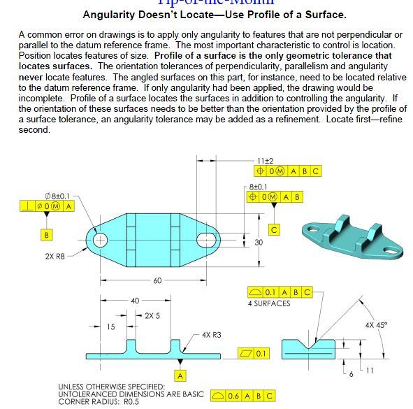
Continue to Site

Eng-Tips is the largest engineering community on the Internet

Intelligent Work Forums for Engineering Professionals

  • Congratulations SSS148 on being selected by the Eng-Tips community for having the most helpful posts in the forums last week. Way to Go!

angularity question

Status
Not open for further replies.
Replies continue below

Recommended for you

AndrewTT,

It depends on what you need to specify. A .006" angular error over a height of .015" is very sloppy. If your slot faces are WRT datum[ ]A only, all sorts of weird shapes are permitted, within the other tolerances on the drawing.

Your .047[±].005" dimension will be hard to inspect, since the corners will be rounded. If this were my part, I would be looking for a way to use a profile tolerance.

--
JHG
 
So, in theory, do I get a different tolerance zone if I specify angularity to datums A,B,C then if I only specify to datum A? Assume that I do not want to use profile.
 
AndrewTT said:
So, in theory, do I get a different tolerance zone if I specify angularity to datums A,B,C then if I only specify to datum A? Assume that I do not want to use profile.

You will get mobility of the TZ (the TZ will be the same, but will be allowed to move for the remaining the degrees of freedom datum A is not capable to stop/ arrest.

Not sure what means....I do not want to use profile?
Why? if the profile is the appropriate (per the standard), why not?

 
For this particular example I just wanted to learn more about angularity and wanted to keep the discussion focused, that is all.

However, the biggest difficulty that I have run across when using profile (when related to datums) is that it controls too much in some applications. Example would be profile controlling several surfaces, some that need tight tolerances while others can be held much looser. Now the tight tolerance feature drives the tolerance zone for the less important features and can increase cost. I am a big fan of the concept of non-uniform profile tolerance zones to solve this problem (tight where you need it, loose where you don't) but they can make a drawing seem cluttered with all the extra basic dimensions and phantom lines.

I have had a few parts at my work where profile seemed the obvious choice but we went in a different direction for the reasons stated above.

2.1.1.1 Postional Tolerancing Method - Preferably, tolerances on dimensions that locate features of size are specified by the positional tolerancing method described in Section 7. In certain cases such as locating irregular-shaped features, the profile tolerancing method described in Section 8 may be used.

I don't put too much into the above wording from the standard but so far, in my very limited use of GD&T, I have had no issues using position and run into a few tricky situations when attempting to use profile.

For the drawing in question I would take position and angularity over a non-uniform profile if they result in the same tolerance because the drawing would be more legible. I'm sure the QA guys might have a different view.
 
greenimi - Technically an angularity t.z. should never be fully arrested because it only orients and does not locate. So, I'm back to my original question, if you use angularity here, what datums need to be called out and what datums should be left out of the FCF? Is datum A sufficient or do you need A, B, C?
 
1.) Can you tell us more about the design requirements? why the angularity should be refined from the location control?
Is the feature in question, already located? By what?

2.) See also Fig. 6-4 - (2009) where datum feature B is invoked to constrain an additional rotational degree of freedom of the DRF.
 
AndrewTT,

You use the angularity specification when the angle is very much more important than the position or profile. Crunch your numbers. Your angularity specification allows your faces to be angled opposite to the way you have shown them.

--
JHG
 
I should always just start with the long version, lol.

For this particular part...

I had parts made (to a non-GD&T drawing). The parts worked perfectly. The angle on the groove was 80°+/-1° on the drawing. After testing the parts were measured and the angle was determined to be 85°. No big deal, the parts work, I'll just adjust the angle tolerance on the print. Then the project goes on hold for a while.

Now fast forward to a time when my company has decided that we will use GD&T...

The project gets picked back up. I work on a GD&T version of the drawing. I quickly put a angularity tolerance (as a place holder mainly) on the drawing so that I can get feedback from the forum. This angularity tolerance will allow an 85° surface so that a functioning part will not be rejected by QA upon measurement, but as pointed out will also allow for an opposite facing angle.

If I were to use profile for the groove, and the angled walls of the groove, the tolerance would be .006 (.003 inboard and .003 outboard) as dictated by my groove depth, which is currently +/- .003. Or would it be .005 (.0025 inboard and .0025 outboard) as dictated by my groove width which is currently .047 +/- .005? Either of these values would be too large for the angled wall, as already stated. This is the problem I run into when attempting to use uniform profile tolerance zones. Not discussed yet is that my groove does not have to be perfectly centered. It can vary slightly off of center and the part will still work (as seen in the position tolerance of .010). If I build that into a uniform profile tolerance zone then the tolerance would get even larger and allow for an even worse angled wall.

I don't believe that I can fix this with a composite profile or multiple single segment profile so that leaves non-uniform profile or position/angularity. Which is why I was interested in what datums I need for the angularity FCF.

Also, keep in mind that the larger my uniform profile tolerance gets the more parallelism to datum A I lose on the groove floor, which is important.
 
AndrewTT,

The angularity FCF shown in your drawing is certainly valid. It sounds like you're only interested in controlling the relationship to datum feature A, so the datum feature reference should be fine as it is. It's hard to know for sure without more information about the part function though.

Any additional datum feature references that constrain additional rotational degrees of freedom of an angularity tolerance zone will change the meaning of the requirement. Datum feature B in you example does not do this, so referencing it as secondary won't change anything.

The .047 dimension refers to theoretical intersections at the bottom of the groove, right? If so, it seems rather dubious to me to consider it a feature of size, which it must be to have a position tolerance.


pylfrm
 
We had this FOS vs. not a FOS discussion here and ended up settling on that it could be treated as a FOS - not saying that we are correct.

Agree or disagree:

1) If the groove met the angled wall with no radius then the groove is definitely a FOS (a set of opposed parallel elements).

2) If the groove had perpendicular walls it is a FOS, even with a radius.

If you put a width dimension on the top of the groove, where there is no radius, instead of the bottom, is that a FOS (a set of opposed parallel elements)?
 
Back to my confusion on angularity. I guess it is stemming from figures 6-1 and 6-8 in the 2009 standard. Why does the FCF in 6-8 have A,B and the FCF in figure 6-1 only have A? It appears that they produce the same tolerance zone. What is B doing for you in 6-8? Why don't you need B in 6-1?
 
AndrewTT said:
It appears that they produce the same tolerance zone. What is B doing for you in 6-8? Why don't you need B in 6-1?


To stabilize the tolerance zone for measurement.
 
Capture_g18gn5.jpg
 
AndrewTT,

I consider the FOS treatment dubious because the definition of actual mating envelope involves contact with surfaces at highest points, but the dimension where the position tolerance is attached refers to theoretical intersections instead of actual surfaces.

In my mind, there is a distinction between the groove feature in general and the width between the two theoretical intersection lines. I'd say neither one is a FOS regardless of as-produced edge condition, but I doubt the conclusion you've reached will cause much trouble in reality.

AndrewTT said:
2) If the groove had perpendicular walls it is a FOS, even with a radius.
Assuming you mean parallel to each other, then the groove width would be a FOS.


AndrewTT said:
Why does the FCF in 6-8 have A,B and the FCF in figure 6-1 only have A? It appears that they produce the same tolerance zone. What is B doing for you in 6-8? Why don't you need B in 6-1?

The secondary datum feature referenced in Fig. 6-8 constrains the third rotational degree of freedom. If it were not included, a part where the hole axis is 60 degrees from datum A, but parallel to datum B, would meet the requirement. That would be a drastically different tolerance, but still equally valid.

In Fig. 6-1, the same principle applies. Rotation in the plane of datum A is unconstrained, so the toleranced surface could be perpendicular to the vertical surface on the left and still meet the angularity requirement.


pylfrm
 
OK, I hope this makes sense...

1) assume that the slot width is a legit use of position for the sake of my questions coming below.

2) The slot width is my third datum (C).

3) If I wanted to include more datums in the angularity FCF I could reference [A, B, C]. This would yield a tolerance zone that is 80° from A and aligned with the slot, correct?

4) If I just call out [A] then I get a tolerance zone that is 80° from A but can revolve around datum axis B, correct?

5) Calling out [A, B] makes no sense and gives me nothing more then just calling out [A] because datum B yields two perp. planes (both perp. to A) but we don't know their orientation without C, correct?

So, finally, my options for angularity FCF are [A] or [A, B, C]. The difference between the two is only the ability of the tolerance zone to rotate about B or not. Of course, the location of the each tolerance zone is not fixed since they are angularity tolerances.
 
AndrewTT said:
3) If I wanted to include more datums in the angularity FCF I could reference [A, B, C]. This would yield a tolerance zone that is 80° from A and aligned with the slot, correct?
Correct, with a subtle difference due to the secondary datum feature reference.

AndrewTT said:
4) If I just call out [A] then I get a tolerance zone that is 80° from A but can revolve around datum axis B, correct?
Correct.

AndrewTT said:
5) Calling out [A, B] makes no sense and gives me nothing more then just calling out [A] because datum B yields two perp. planes (both perp. to A) but we don't know their orientation without C, correct?
Correct, this would be equivalent to referencing A only.

AndrewTT said:
So, finally, my options for angularity FCF are [A] or [A, B, C]. The difference between the two is only the ability of the tolerance zone to rotate about B or not. Of course, the location of the each tolerance zone is not fixed since they are angularity tolerances.
Correct, except |A|C| is an option as well. Referencing B as secondary changes the way that C is used to constrain the third degree of freedom.


pylfrm
 
No one has mentioned this, but why not composite profile? Location, orientation, form and size call all be refinements of higher precedence FCF.

Certified Sr. GD&T Professional
 
mkcski,

The OP said :"Assume that I do not want to use profile."

Now, if he does not want to use profile (not sure why, but that is a different story) then ...............composite profile is not in the same boat?

 
In order to see what the datum references are doing use constraint analysis. Each feature starts with X,Y,Z, AX, AY, and AZ degrees of freedom. Each datum reference controls any other unconstrained degree that has not been constrained earlier in the feature control frame. Certain degrees will not affect the necessary degrees. For example, angularity ignores X, Y, and Z constraints, so those can be ignored.

Just make a list and then for each datum reference, in turn, strike off the degrees of freedom it controls to see what remains. It isn't required to control all of them; it may not matter for any particular feature.

This technique should be explicit in the next version of the standard; it should have been included in the first versions. It is more important than the fixed and floating calculations and are not considered in the decision trees.

Since 'Y14.5 has no examples of edges as suitable FOS candidates, it is worth adding that as an exception to the note that the drawing is in accordance with 'Y14.5.
 
Status
Not open for further replies.

Part and Inventory Search

Sponsor