Continue to Site

Eng-Tips is the largest engineering community on the Internet

Intelligent Work Forums for Engineering Professionals

  • Congratulations waross on being selected by the Eng-Tips community for having the most helpful posts in the forums last week. Way to Go!

Beam connection stability 7

Status
Not open for further replies.

Vrpps EIT

Structural
Aug 21, 2018
58
Hi All,

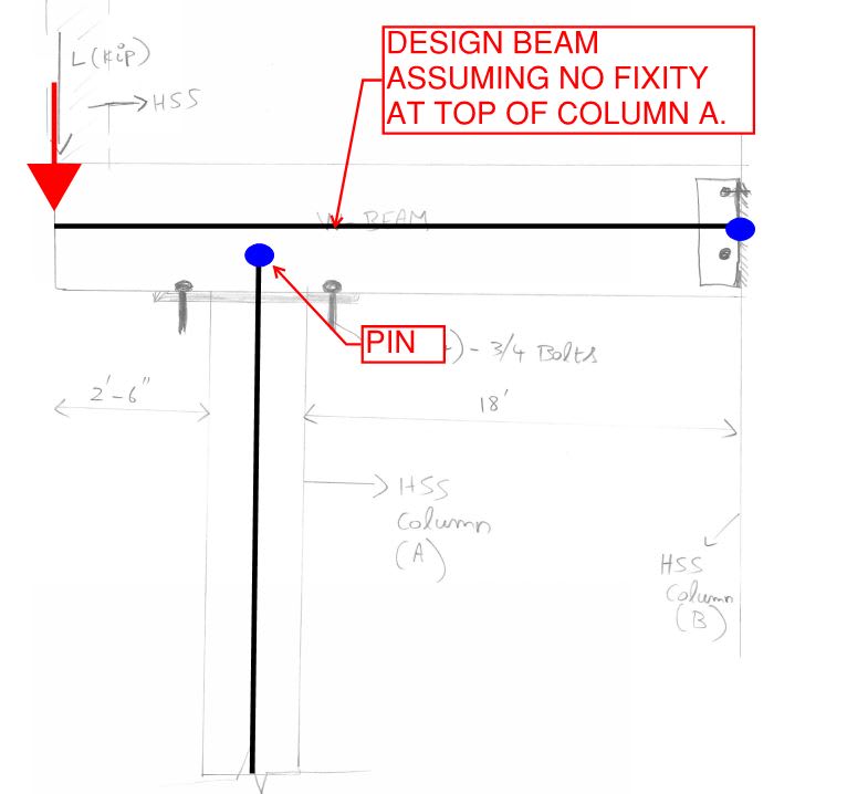
Attached the situation in the pic, under this loading, when the overhang portion has a column on top of it and has a point load. This creates a moment at the beam and column-A connection. which in turn will create an uplift load. So, this uplift will be resisted by the beam & column-B connection at end of the beam which is fixed there or the four bolts that are connected at beam column-A connection? Or in simple terms what tensile force should the 4 bolts at column support A near the overhang to be checked for is it the reaction force that support will carry?
I can see it as a tower crane with balancing counter jib but I am missing something here.

Thank you for your time!
 
 https://files.engineering.com/getfile.aspx?folder=2e3d4853-5d88-4ea1-a52b-861a35338f7a&file=Scan001_(5).jpg
Replies continue below

Recommended for you

It's dependent on relative stiffness, right? Not sure I can tell you how to design those connection bolts until I know how the moment distributes to the beam vs column.

Some of the moment will go into the column based on the relative flexural rigidity of the column. And, some will go into the beam and backspan based on the relative rigidity of that beam.

The relative rigidity of the two is based on column length vs beam length. Column EI vs Beam EI and end connectivity (pinned vs fixed) of the beam vs column support.

 
Josh- The moment on the beam there at support-A will be the load * the distance of 2'-6" (overhang) and this sits on top of the column. But in general when you have your bolt connection to connect a beam sitting on top of the column what load do you take for your design?
 
Nineteen out of twenty structural engineers and your dentist are going to do it like this, ignoring the moment at the top of column A entirely.

c01_oycfsr.jpg
 
Kootk- so the tensile load on those bolts will be from?
 
You need a analysis to get the numbers for what you need. You are correct in that there would be a potential transfer of moment at the cap plate. (Potentially resulting in a uplift load on 2 of the bolts. Although I would think the vertical [down] load would probably eliminate that.) But a lot of what you are asking needs a quick run in some type of software/spreadsheet.

Kootk's way is pretty good. I would add on to it a quick & dirty calc to see what is the max moment that could transfer at the column.....and see if there is any potential tension on the bolts.

 
Thanks, will check it for pin connection. Just an additional one, since this overhang column is an addition to the existing beam and this creates higher reaction force on the existing column-A should this column-A also to be checked for it's uplift capacity at the foundation wall where it is anchored down with bolts on top of the wall ?
 
Column A should be checked for the extra load that it will see. It seems to me, however, that extra load will be compression and not uplift. Column B, and the connection to it, should probably be checked for a new increment of uplift.
 
Kootk- why I asked uplift was the joist runs parallel to the beam so most of the load acts only at that corner where the overhang is and it doesn't have that much of weight above it as well
 
KootK I'm starting to think this thing might be an exterior overhang thus see a fair bit of uplift. If your looking for tensile forces to the bolts under uplift conditions it's simply your reaction/# bolts. Plate needs to be designed for the uplift force...super simple calc.
 
If your looking for tensile forces to the bolts under uplift conditions it's simply your reaction/# bolts.

At that column, it would be the moment divided by the distance from the bolt lines to each other. (I.e. the couple.) Tension on one side, compression on the other. Added to that would be the vertical reaction at the post.

You (actually) could make the case that the couple would be from one bolt line to the face of the column on the opposite side.
 
WARose- that couple creates tension on one side (creating an upward pull) and compression on the other. But if I am not mistaken you're saying that the download from the overhang column will tally out this upward pull is that right? Also, I will do the calc. as well. Thanks
 
But if I am not mistaken you're saying that the download from the overhang column will tally out this upward pull is that right?

Potentially. (Especially with such a short [approx. 2'-6"] overhang.) You just have to grind the numbers to find out.

 
Another way to look at it (although it is almost certainly not necessary) would be to calculate the rotation of the beam at the location over column A, then find the strain in the bolts based on that rotation. That's another way of saying find the displacement of the beam at the bolts relative to the displacement of the beam at column A (~zero), get strain in the bolts, then of course the stress in the bolts.

Like Kootk said, 99 out of 100 engineers would just say "it's a pinned connection". I'd be more concerned about the stability of the beam itself (is it restrained against rotation along its longitudinal axis). I.e., make sure the column doesnt move 'in and out of the page'.
 
KootK said:
Nineteen out of twenty structural engineers and your dentist are going to do it like this, ignoring the moment at the top of column A entirely.

And maybe 19 times out of twenty that shouldn't be an issue but if your members are slender then you can readily get unwanted and potentially problematic moment transfer into your column. I had this exact scenario occur many years back on a single story structure. The rafters were light and continuous across 40m with several light square hollow sections. The hollow sections ended up bending like bananas.

We have plenty of computing power available to use. I see the need to make a potentially less conservative assumptions of a pinned connection when we can do better.
 
I have a sense that the hotel in New Orleans that collapsed did so because some slender tube columns were bending (as evidenced in a few pre-collapse photos) due to excessive bending of the floor system.

 
In case of a moment transfer happening at that beam-column junction, how much % of the moment is that column to be checked for? is it that entire moment or will the vertical download reduce the moment? Thank you
 
Status
Not open for further replies.

Part and Inventory Search

Sponsor