Continue to Site

Eng-Tips is the largest engineering community on the Internet

Intelligent Work Forums for Engineering Professionals

  • Congratulations waross on being selected by the Eng-Tips community for having the most helpful posts in the forums last week. Way to Go!

Beam connection stability 7

Status
Not open for further replies.

Vrpps EIT

Structural
Aug 21, 2018
58
Hi All,

Attached the situation in the pic, under this loading, when the overhang portion has a column on top of it and has a point load. This creates a moment at the beam and column-A connection. which in turn will create an uplift load. So, this uplift will be resisted by the beam & column-B connection at end of the beam which is fixed there or the four bolts that are connected at beam column-A connection? Or in simple terms what tensile force should the 4 bolts at column support A near the overhang to be checked for is it the reaction force that support will carry?
I can see it as a tower crane with balancing counter jib but I am missing something here.

Thank you for your time!
 
 https://files.engineering.com/getfile.aspx?folder=2e3d4853-5d88-4ea1-a52b-861a35338f7a&file=Scan001_(5).jpg
Replies continue below

Recommended for you

I just did a quick check, if the moment in the column is around 1 ft-k, the code specified minimum will cover (with e=b/6, b=5").
 
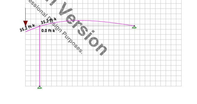
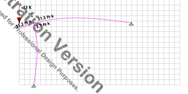
2-D verifications (W10x30 Beam, HSS5x5x3/16 Column):

Pinned Beam-Column Joint
pin_ic0pga.png


Rigid Beam-Column Joint
fix_q0sck1.png
 
retired13- What is the software in the above image?
 
RISA 2D. You can download free trail.
 
The load at the end of the cantilever is applied by a HSS column. Everyone so far seems to be regarding its connection with the beam as a perfect pin when in fact it cannot be. If that HSS is rigidly connected to the beam, it too must take moment, for which it should be designed. Also, the moment taken by the end column reduces the cantilever moment.

Is there a valid reason to be so concerned with one connection while completely ignoring another?

BA
 
Also, the moment taken by the end column reduces the cantilever moment.

BAretired - is this really true? Usually the moment in a cantilever is entirely independent of the assembly beyond (behind) the cantilever right?

In this case, the cantilever moment is always P x (Cantilever Length).

 
retired 13, what is the rotation of the beam at the column in your pinned example?
 
JAE,

The end column will reduce the cantilever moment if the slope is as shown in retired13's Risa 2D output. If the span moment is dominant, i.e. if it creates an upward slope in the cantilever, then the end column will increase the cantilever moment. In the special case where the slope is zero as a result of the simultaneous span and cantilever loading, the end column stiffness will have no effect on the cantilever moment.

BA
 
Rabbit12,

Here is the deflection table. Beam L-R jt 1-3, column base jt 4

pt_moggvs.png
 
BA - when you say "end column" are you talking about the column at the end of the cantilever?


For the rigid connection model,

pt1_v4djj2.png
 
Yes JAE, I'm saying the end column is the column at the end of the cantilever.

EDIT: All of a sudden, I am realizing that you thought I meant the column at the end of the span. Of course, that column would have no effect on the cantilever moment.

BA
 
And so assuming that the end column is "fixed" to the cantilever, then yes, the cantilever moment might be affected by relative stiffenesses.

Got it thanks

 
BAretired said:
The load at the end of the cantilever is applied by a HSS column. Everyone so far seems to be regarding its connection with the beam as a perfect pin when in fact it cannot be. If that HSS is rigidly connected to the beam, it too must take moment, for which it should be designed. Also, the moment taken by the end column reduces the cantilever moment.

Is there a valid reason to be so concerned with one connection while completely ignoring another?

In my experience the simple snug tight bolted cleat connections exhibit more rotation and less stiffness than axially loaded cap plate connections. Though I would be happy to be proven wrong and I believe it will make an interesting discussion. If anybody has research on this I am listing.


**One thing to note that sometimes a rigid connection on a column can actually REDUCE the applied moment to the column compared to a typical eccentric cleated connection. This of course depends on the eccentricity, the loads and the members involved.
 
BARetired said:
Everyone so far seems to be regarding its connection with the beam as a perfect pin when in fact it cannot be. If that HSS is rigidly connected to the beam, it too must take moment, for which it should be designed

Are you saying the column should be designed for the moment, or the connection?
 
Human said:
In my experience the simple snug tight bolted cleat connections exhibit more rotation and less stiffness than axially loaded cap plate connections

Definitely. A cleat plate is much closer to a pin than a cap plate. The bolts are in bearing with slop in the holes, and the cleat itself is a lot less stiff than the member.
 
In practice, it is usually beneficial if you can use simple bolted connection. However, the column inevitably will experience some moment due to rotation of the beam against the edge of cap plate. Therefore, it is advisable to design the beam for the full moment, and design the column with a moment equal to P*b[sub]p[/sub]/2, b[sub]p[/sub] is the width of the cap plate.
 
Tomfh said:
Are you saying the column should be designed for the moment, or the connection?

The connection is intended to be a pin, but some moment transfer is inevitable. The column at the end of the cantilever should be designed with that moment in mind.

BA
 
human909 said:
In my experience the simple snug tight bolted cleat connections exhibit more rotation and less stiffness than axially loaded cap plate connections. Though I would be happy to be proven wrong and I believe it will make an interesting discussion. If anybody has research on this I am listing.

There has been no mention of "simple snug tight bolted cleat connections". The OP's sketch indicates an HSS column at the end of the cantilever with no description of its connection to the beam. There is no indication of the load on that upper column, so it is possible that a cap base plate would be needed, not to mention a stiffener under one or both walls of the HSS.

It is inconsistent to quibble about ignoring the moment on the lower column while happily ignoring the moment on the upper column. How could you be proven wrong and how could anyone have research on something as ethereal as this?


BA
 
BA,

Do you mean there is a HSS column on the tip of the cantilever?
 
Status
Not open for further replies.

Part and Inventory Search

Sponsor