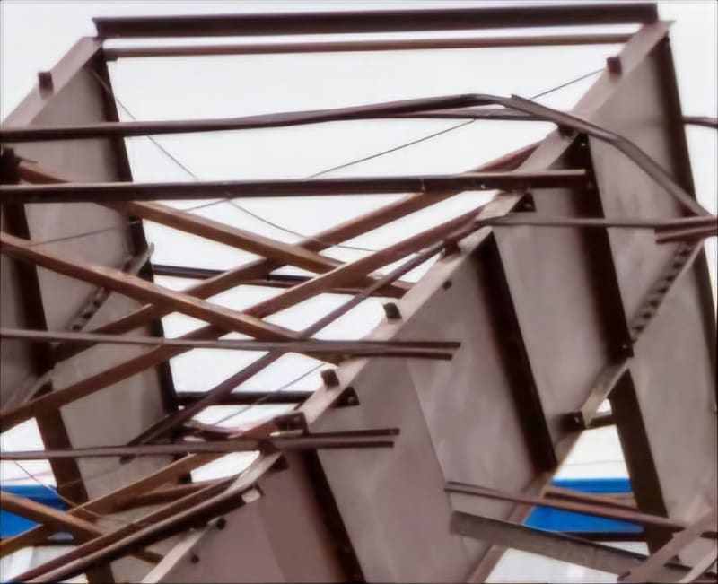
Hangar under construction collapsed killing 3 and injuring more.
Navigation
Install the app
How to install the app on iOS
Follow along with the video below to see how to install our site as a web app on your home screen.
Note: This feature may not be available in some browsers.
More options
Style variation
-
Congratulations MintJulep on being selected by the Eng-Tips community for having the most helpful posts in the forums last week. Way to Go!
You are using an out of date browser. It may not display this or other websites correctly.
You should upgrade or use an alternative browser.
You should upgrade or use an alternative browser.
Boise Airport Hangar 7
- Thread starter TigerGuy
- Start date
- Status
- Not open for further replies.
Attached is the Civil Complaint against Big D Builders, Inland Crane, etc. filed July 9.
Brian Malone
Industrial
The civil complaint has a rather damning list of alleged errors by the principals involved. If they all (or many) are true then it looks like at least three companies took risks (and dragged in a fourth) to meet schedule but lost the gamble. They probably could have finished the job without issue except for the wildcard factor of the weather which they had no control of.
davidbeach
Electrical
Murphy loves a challenge...
When one this sentence into the German to translate wanted, would one the fact exploit, that the word order and the punctuation already with the German conventions agree.
-- Douglas Hofstadter, Jan 1982
When one this sentence into the German to translate wanted, would one the fact exploit, that the word order and the punctuation already with the German conventions agree.
-- Douglas Hofstadter, Jan 1982
Brian Malone
Industrial
The windy conditions lined up the Swiss cheese holes.
Sym said:Once a structure of that mass deforms enough to snap the cross bracing, are they going to be able to pull it back into shape with a come along or would they need to utilize additional supports?
If the structure has just begun to buckle and some restraints are broken, but it hasn't yet yielded (i.e., it is still within its elastic limit), it can be resupported, likely using a crane, and then rebraced. However, if the structure has buckled past its elastic limit and the beams are permanently deformed out of plane, simply resupporting it will not restore the correct shape. This situation is fairly common with slender, long-span beams, which can be quite flexible in the out of plane direction before restraints and sheeting are installed. Presumably they were counting on straightening these ones up, before it all got away from them.
A reddit user suggested the collapse mechanism was 3rd order Euler buckling. I see it as 1st order between an east and west constraint. 3rd order is unlikely as it requires 9x the force while the structure has to successfully resist the first two orders. The buckling initiates in the top flange, which is under compression. The lower flange does not buckle as it is under tension and merely attempts to straight line. This results in the beams laying over in one direction on the centerline and then in the opposite direction as it ties into the constraints, a clever illusion of third order.
This may also reveal the cause of collapse being the absence of cross bracing where the cranes were located through the center half of the structure. This may be an unfortunate oversight given they had to remove the cranes before they could fall back and reinforce that portion of the structure.
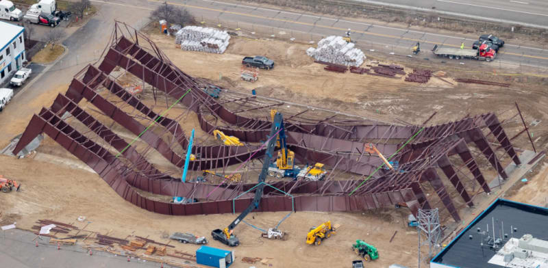
Green lines represent east and west constraints of buckling, fuscia the centerline and cyan the remaining crane support.
This may also reveal the cause of collapse being the absence of cross bracing where the cranes were located through the center half of the structure. This may be an unfortunate oversight given they had to remove the cranes before they could fall back and reinforce that portion of the structure.

Green lines represent east and west constraints of buckling, fuscia the centerline and cyan the remaining crane support.
Civil Complaint incuding Exhibits from constructiondive.com article, here (28.9 MB). i.e. all construction dwgs and details, police reports, etc.
The compaint makes some specific and bold assertions but upon initial review, I don't see the basis for them. Perhaps pairs of 300' long beams were just too slender and/or Big D wasn't prepared for the implications.
The compaint makes some specific and bold assertions but upon initial review, I don't see the basis for them. Perhaps pairs of 300' long beams were just too slender and/or Big D wasn't prepared for the implications.
I've broken out the Exhibits into more manageable chunks
Exhibit A - Approved City Plans
Exhibit A - Approved City Plans
Exhibit C - SBS Modified Install Set
Exhibits B and D (Part 1)
Exhibit D includes the Boise Police Reports
Exhibit D includes the Boise Police Reports
Sym said:The compaint makes some specific and bold assertions but upon initial review, I don't see the basis for them.
What complaints did you have in mind? There are concerns about unauthorised bracing changes, but the revised plans seem to show more bracing than the approved ones?, so I'm not sure how that's relevant. There are also what appear to be some irrelevant comments about things like paint color.
Reading the witness statements it sure seems like the main issue was a lack of temporary support, resulting in serious beam instability in the temporary condition. The drawings appear to show a lot more bracing and purlins than were actually in place at the time of the collapse. It sounds like it was buckling in various place. Those witness statements say they were trying to fix it with cranes, temporary straps, winches, and additional purlins, to straighten it all up, but that it got away from them.
There is a lot to discuss but I'm no structural expert at design options. The "knife" comment was particularly notable but I see that terminology in the OEM dwgs so that's why the civil suit plays off of it.
Some differences to start (please excuse my use of dwg. collages):
OEM calls for rigid x-bracing across four bays, concentrated more to the corner extremity than the center line.
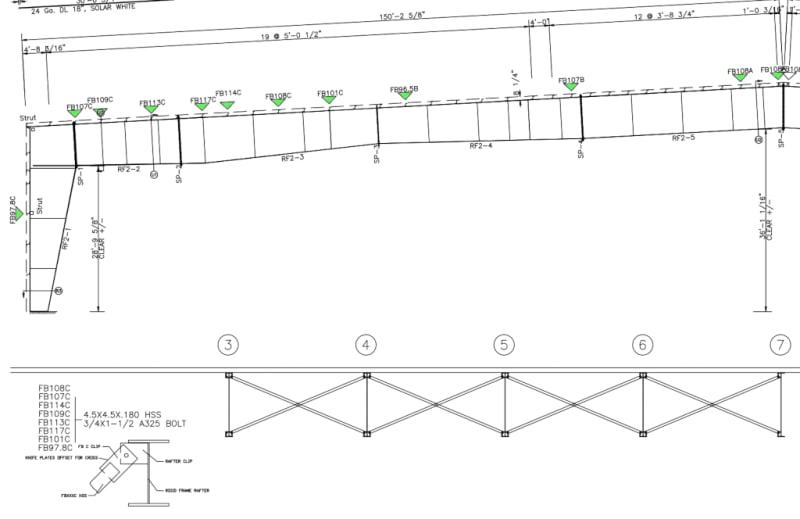
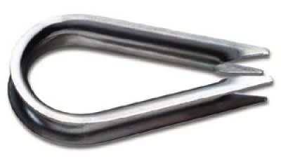
SBS utilizes rigid x-bracing for the corner extremity but then uses a cable tension system towards the center line. If this is at all functional, I see it as more trouble than it's worth. Furthermore, what is a cable brace grip? If there is no protection for the cable eye, that would lead to knife like cutting of the tensioned cable.
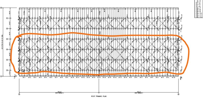
Also, the x-bracing isn't continuous across four bays, rather every other bay. As I mentioned earlier, these 300 foot beam assemblies in pairs are likely too slender to resist buckling and require the support of additional bays.
From all the site photos, it appears that these details are indeed what was used. The next question is were all of these components installed in sequence with the erection process or were some omitted to be filled in later?
Edit: These details also support my theory of 1st order buckling between an east and west constraint, where the rigid x-bracing toward the corners provided substantial stability.
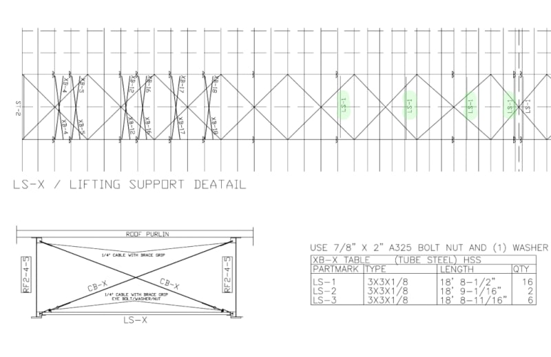
Some differences to start (please excuse my use of dwg. collages):
OEM calls for rigid x-bracing across four bays, concentrated more to the corner extremity than the center line.

SBS utilizes rigid x-bracing for the corner extremity but then uses a cable tension system towards the center line. If this is at all functional, I see it as more trouble than it's worth. Furthermore, what is a cable brace grip? If there is no protection for the cable eye, that would lead to knife like cutting of the tensioned cable.
Also, the x-bracing isn't continuous across four bays, rather every other bay. As I mentioned earlier, these 300 foot beam assemblies in pairs are likely too slender to resist buckling and require the support of additional bays.
From all the site photos, it appears that these details are indeed what was used. The next question is were all of these components installed in sequence with the erection process or were some omitted to be filled in later?
Edit: These details also support my theory of 1st order buckling between an east and west constraint, where the rigid x-bracing toward the corners provided substantial stability.


Yes the change from four bays to two bays within the depth of the webs wouldn't have helped. Presumably that's what they're referring to.
I was more looking at the in-plan bracing in the final configuration, which to me is where the primary lack of stability exists. In the final case you have a relatively wide bracing assembly, 3 bays wide, which would stop the whole thing falling over.
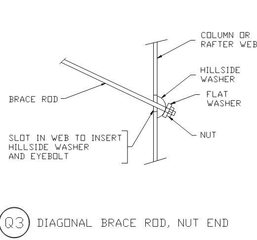
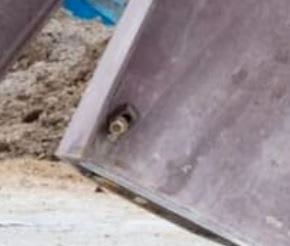
As for the cable grips, I presume they are referring to the hillside washer detail: (edit: It actually seems to refer to the LS cable bracing grips)
I was more looking at the in-plan bracing in the final configuration, which to me is where the primary lack of stability exists. In the final case you have a relatively wide bracing assembly, 3 bays wide, which would stop the whole thing falling over.

As for the cable grips, I presume they are referring to the hillside washer detail: (edit: It actually seems to refer to the LS cable bracing grips)


The cable grips are called for in the LS-X tension cable detail in the SBS collage I posted above. Depending on the specific item the designer refers to, it may not include the cable protection.
Did you find a connection detail for in-plan bracing?
Did you find a connection detail for in-plan bracing?
- Status
- Not open for further replies.
Similar threads
- Question
- Replies
- 12
- Views
- 14K
- Replies
- 18
- Views
- 1K
- Locked
- Question
- Replies
- 7
- Views
- 719
- Locked
- News
- Replies
- 24
- Views
- 2K
- Replies
- 81
- Views
- 9K

