Hangar under construction collapsed killing 3 and injuring more.
Navigation
Install the app
How to install the app on iOS
Follow along with the video below to see how to install our site as a web app on your home screen.
Note: This feature may not be available in some browsers.
More options
Style variation
-
Congratulations TugboatEng on being selected by the Eng-Tips community for having the most helpful posts in the forums last week. Way to Go!
You are using an out of date browser. It may not display this or other websites correctly.
You should upgrade or use an alternative browser.
You should upgrade or use an alternative browser.
Boise Airport Hangar 7
- Thread starter TigerGuy
- Start date
- Status
- Not open for further replies.
Sym said:Edit: These details also support my theory of 1st order buckling between an east and west constraint, where the rigid x-bracing toward the corners provided substantial stability.
Yes I think you're right that the zone with the cable cross bracing is where it was too soft. The rigid cross braced zones seem to have fared much better.
As for your point about the brace grip, you're right that it doesn't seem to be spelled out anywhere. They may have just looped the cable through and used standard wire rope grips.
Sym said:Likely tabs under the flange
Why don't you think it's detail Q3?
All that plan bracing shown on the roof plan is actually diaphragm bracing. So I suspect none of that would be installed until frame erection is complete and maybe until the purlins are on. Typically they don't rely on the roof deck as a diaphragm.
Usually any temporary erection bracing is entirely the responsibility of the erector / contractor. Most structural drawings have notes to the effect of "the structural system is designed to function as a complete system. Contractor is responsible for all temporary bracing....etc etc". That temporary bracing would pretty much be left in place until all the permanent horizontal and vertical bracing is installed.
And yes, I'd suspect Tomfh is correct. Most bracing is just installed through a hole in the web of the frames with a hillside washer and nut on the opposite side.
Tomfh (Structural) 7 Aug 24 06:38 said:I was more looking at the in-plan bracing in the final configuration, which to me is where the primary lack of stability exists.
Between beam lines 3 and 4, none of the in-plan cross bracing would be installed initially during erection as that was the opening for the cranes. This fundamentally disrupts the stability of the system, leaving three independent beam pairs, any one of which could deflect and drag the remainder of the structure with it.
Was the CB roof bracing present within the central zone of the beam pairs? I.e. The zone between the green lines where the buckle is most severe? I can see those CB rods in the end zones in the photos but can’t make it out in the central zone.
Dold said:All that plan bracing shown on the roof plan is actually diaphragm bracing. So I suspect none of that would be installed
You can see that some of it is installed within the beam pairs they have put up. I can’t see whether it extends along the entire length of each beam pair or if some sections weren’t installed yet in the midspan zones where the rafters buckled. Regardless, it (and the purlins) don’t seem to have been installed across the whole of grid 2-5, indicating that it’s reliant on temporary stability. Who’s fault that is remains to be seen. There are references to discussions with engineers in the witness statements, with an all clear and instruction to proceed apparently having been given.
Sym said:I've looked hard and can't see them. The end results suggest they aren't ther
If they weren’t there that would be a fairly large omission, as there would be no lateral stability for that entire central zone. The LS arrangements could provide some resistance against the beams rolling, but nothing against lateral sway.
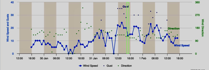
So the next question is why did the structure lean into the wind? Perhaps a latent manifestation of an earlier onset.
Edit: Surprise Answer! The winds were keeping the structure from falling over. It wasn't until the winds abated that the structure collapsed. This has to be said tongue in cheek as the winds likely rattled the structure significantly.

Edit: Surprise Answer! The winds were keeping the structure from falling over. It wasn't until the winds abated that the structure collapsed. This has to be said tongue in cheek as the winds likely rattled the structure significantly.

I think you nailed the primary cause of the collapse being the missing diaphragm cross bracing through the entire center of the structure. I'd be surprised to find some or any or it installed now.
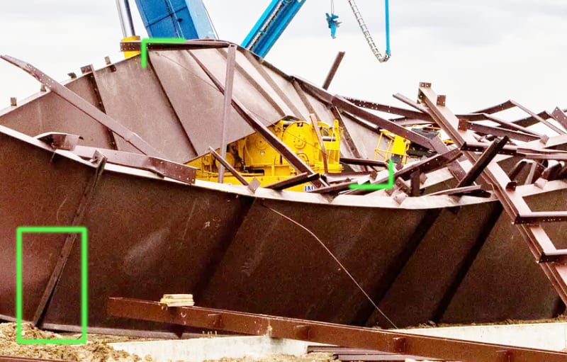
Edit: Uh oh, I spoke too soon.One cross brace LS-X tension cable (between green tabs) and missing bolts (though it may be likely they popped off from the collapse).

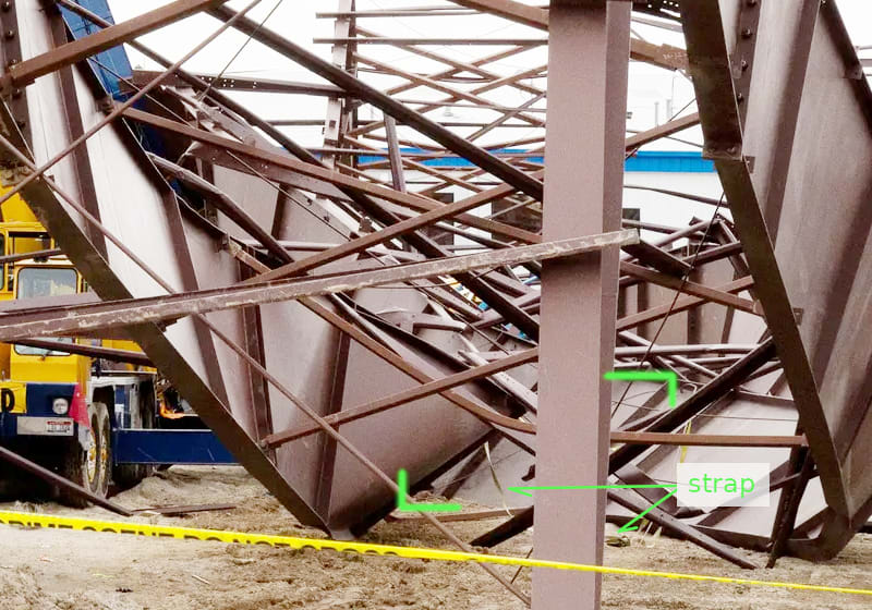
Another cross brace and a strap.

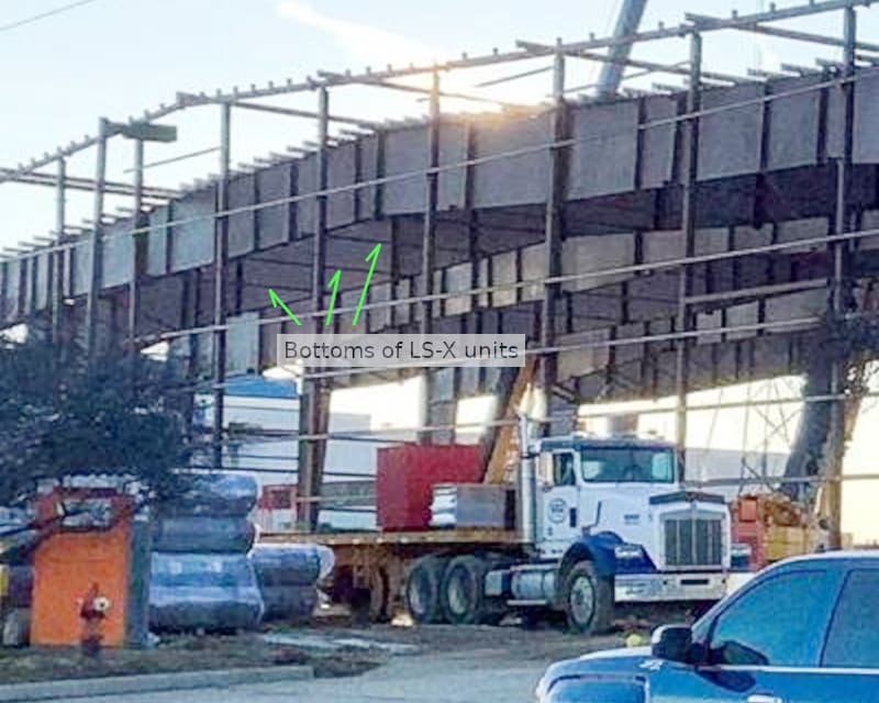
LS-X Brace is visible but the tension cables are not.

Edit: Uh oh, I spoke too soon.

Another cross brace and a strap.

LS-X Brace is visible but the tension cables are not.

Sym said:Edit: Uh oh, I spoke too soon. One cross brace and missing bolts (though it may be likely they popped off from the collapse).
Which cross brace and missing bolts? There's a few things in that photo.
The missing bolts are in the green box. The 300 foot beam is shipped in 10 pieces, 5 each side of center. I believe they were assembled into east and west halves before being raised and bolted at the center and to the top of the columns. The assemblies should be fully bolted and tightened prior to being raised. The connection plates in the photo appear to be separated, indicating missing bolts (at the bottom).
The green tabs indicate a length of brace rod (between) in the central area in question. I believe it would be part of the line 4 and 5 beam pair.
The second photo shows another length of brace rod, also part of the line 4 and 5 beam pair in the central area in question. I've tried to ignore the brace rods that are obviously closer to the corners.
Although the LS-X lower brace can be seen in the lower photo, I can't find the equivalent in any of the collapse photos, let alone the tension cables.
(I guess the green tabs look like arrows. That wasn't what I had in mind, they were just to frame the ends of the brace rod of interest)
Sym said:The green tabs indicate a length of brace rod in the central area in question. I believe it would be part of the line 4 and 5 beam pair.
The one in the first photo looks like part of the LS cable bracing as opposed to diaphragm bracing.
But yes I can see the diaphragm bracing in the other photos. It would be interesting to know what the pop noises were. The LS bracing, the diaphragm bracing, or both.
I think you're right on the first one. It's disappointing not having better engineering analysis from the likes of OSHA, especially when workers are being injured and worse from poor construction techniques.
The final position of the beam lines still indicates a lack of diaphragm cross bracing.
The final position of the beam lines still indicates a lack of diaphragm cross bracing.
XR250 said:Is it possible that is simply not reasonable to assume that a structure of this size with such slender members cannot be erected with the current pool of labor?
I can see a situation where the EOR gets sued for just this very reason.
XR250, can you explain a bit more, I'm not sure I understand what you are saying here.
One thing I was kind of curious about. If I remember right, in the OSHA citation, they basically said "it wasn't adequately braced during erection, so it fell down". Of course, the presumption is, that had it been adequately braced, it all would have been okay. But is that actually true? Did OSHA actually go through the building design (or have consultants go through it) and conclude that the design itself it was all correct and that erection issues were the sole problem, or did they simply not look into the design? The OSHA citation didn't address the design itself one way or the other.
I'm remembering the posts on the Hard Rock Casino collapse, which, as I recall, failed during erection, but the presumption was that the building design itself was inadequate, and I was wondering if that had been ruled out here.
Come to think of it, was it ever determined what actually went on at the Hard Rock Casino relative to the design? Or is that all still in legal limbo?
- Status
- Not open for further replies.
Similar threads
- Question
- Replies
- 12
- Views
- 14K
- Replies
- 18
- Views
- 1K
- Locked
- Question
- Replies
- 7
- Views
- 701
- Locked
- News
- Replies
- 24
- Views
- 2K
- Replies
- 81
- Views
- 9K
