Navigation
Install the app
How to install the app on iOS
Follow along with the video below to see how to install our site as a web app on your home screen.
Note: This feature may not be available in some browsers.
More options
Style variation
-
Congratulations cowski on being selected by the Eng-Tips community for having the most helpful posts in the forums last week. Way to Go!
You are using an out of date browser. It may not display this or other websites correctly.
You should upgrade or use an alternative browser.
You should upgrade or use an alternative browser.
Bridge failure near Albany NY 15
- Thread starter bridgebuster
- Start date
- Status
- Not open for further replies.
- Moderator
- #21
-
1
- #22
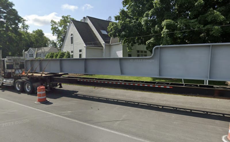
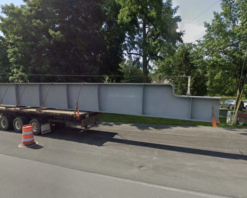
As luck would have it google drove by when the beams were being delivered.
Could the construction loads been higher than the in service loads?
Could the construction loads been higher than the in service loads?
JohnRBaker
Mechanical
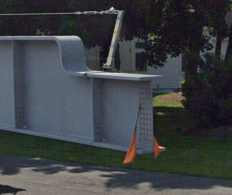
From the images, as compared to the old bridge, the beefed-up section of the new bridge appears to have NOT been long enough to fully span the unsupported portion of the overpass. Tug might have been right in the sense that the span was not perpendicular to road that it was crossing, meaning that either the beefed-up section had to be longer than necessary if the bridge layout was symmetrical or if they were only as long as needed, they needed to be staggered so that they both fully spanned the overpass.
John R. Baker, P.E. (ret)
Irvine, CA
Siemens PLM:
The secret of life is not finding someone to live with
It's finding someone you can't live without
John R. Baker, P.E. (ret)
Irvine, CA
Siemens PLM:
The secret of life is not finding someone to live with
It's finding someone you can't live without
DanKile's Google image shows the beam to be asymmetrical, with (apparently) a bolted joint at one end. One of the Times-Union pics seem to show a bolted splice. Maybe for transport?
The problem with sloppy work is that the supply FAR EXCEEDS the demand

The problem with sloppy work is that the supply FAR EXCEEDS the demand
The original deep section span did not reach - that's why there were supports at the ends of the original deep section of the span. They took out the supports to make the road wider and to shift the sidewalks underneath. then decided to put the weight of the road paving machine and so forth on it.
So - the old span was hit 9 times in the past 11 years, including by a cement truck and won that battle. Someone was smart enough to realize one could not move the sidewalk with the old bridge supports and so duplicated the solution that required the old supports but didn't use them.
I think of Red's opinion from "The 70s Show" - Dumbass.
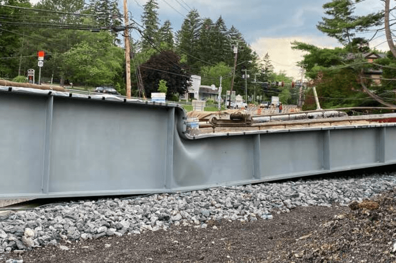
It's pretty close to my favorite failure mode - the can opener, with the shallow section top plate acting as the opener for the more vertical section of the transition. Nice job putting inadequate radii to make that action less abrupt and extra points for buckling the web.
-
1
- #28
More than likely the design - as seemingly bizarre as it is until you realize they were trying to match the general look of the old bridge - would have been more than satisfactory if they'd just thrown in an extra stiffener at the transition. A nice 45 degree stiffener likely would have prevented the buckling and allowed it to carry the loads nicely. That's something a senior engineer should have looked at during a design review and said "hmm...something's off here..."
-
2
- #29
I would have expected an extension of the flange of the shorter section to push into the web of the taller section at a length equal to the difference between the flange heights (a la AISC SCM 15th ed. Figure 9-11.b).
Please note that is a "v" (as in Violin) not a "y".
Please note that is a "v" (as in Violin) not a "y".
-
2
- #33
bridgebuster's original title refers to "forgetting some stiffeners".
SWComposites called it a "horrible design detail"
EdStainless said: "They forgot to take the deep section to the support."
LittleInch said: "Looks to me like they just copied the old one"
3DDave likened it to the phrase: "Dumbass"
And several others....all correct and on target comments.
I just wonder how the "engineer" didn't understand the issue of an interrupted compression flange.
The only other answer is that, in order to maintain their aesthetic goal, they attempted some type of finite element analysis on that web...if they did then obviously did it wrong.
This seems like pure incompetence.
TugboatEng
Marine/Ocean
If the bridge spanned the supports correctly, there would be no interrupted compression flange. I think this is a case of a pre-fabricated bridge being installed incorrectly.
What I find strange is that there doesn't really appear to be any plan to support the bridge. Was it just going to sit on those wood blocks? Surely they wouldn't build the supports after pouring the concrete deck. The bridge did appear to have quite a bit of arch before pouring the concrete. Do they need to pour it before placing the permanent supports due to the length change as the arch straightens?
What I find strange is that there doesn't really appear to be any plan to support the bridge. Was it just going to sit on those wood blocks? Surely they wouldn't build the supports after pouring the concrete deck. The bridge did appear to have quite a bit of arch before pouring the concrete. Do they need to pour it before placing the permanent supports due to the length change as the arch straightens?
I don't think there was meant to be any center support.
Fortuitous timing with the google maps camera here. If you cross the street the bridge girders are still on the truck. And the webs look woefully thin.
[URL unfurl="true"]https://www.google.com/maps/@42.629735,-73.8646742,3a,34.7y,125.7h,83.66t/data=!3m6!1e1!3m4!1sQkQeeDBB8gSERdcrISCQmQ!2e0!7i16384!8i8192?entry=ttu[/url]
The view under the old bridge is informative: Two of the supports got a good whack; one of them got them to add a parallel brace.
The girders on the transport trucks:
The girders on the transport trucks:
- Moderator
- #39
There are other designs available.
Something like this would have given more span and more clearance, until it didn't.
[URL unfurl="true"]https://res.cloudinary.com/engineering-com/image/upload/v1689293341/tips/image004_wglpoh_vo4evt.webp[/url]
--------------------
Ohm's law
Not just a good idea;
It's the LAW!
Something like this would have given more span and more clearance, until it didn't.
[URL unfurl="true"]https://res.cloudinary.com/engineering-com/image/upload/v1689293341/tips/image004_wglpoh_vo4evt.webp[/url]
--------------------
Ohm's law
Not just a good idea;
It's the LAW!
-
1
- #40
- Status
- Not open for further replies.
Similar threads
- Locked
- Question
- Replies
- 69
- Views
- 4K
- Replies
- 4
- Views
- 2K
- Question
- Replies
- 27
- Views
- 24K
- Replies
- 1
- Views
- 5K
- Replies
- 13
- Views
- 13K

![[sad] [sad] [sad]](/data/assets/smilies/sad.gif)
